


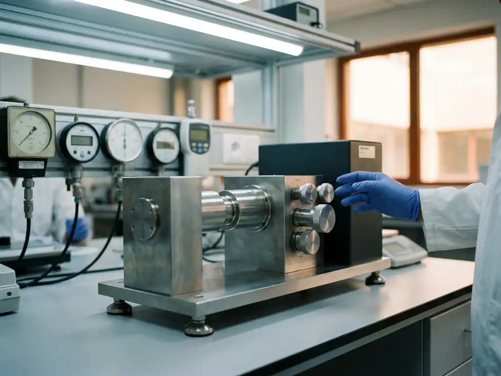
A force test cell data sheet communicates the mechanical, thermal, and electrochemical boundaries within which the cell can operate reliably. Buyers who read these documents carefully can match a cell to their experimental requirements before committing to a purchase. The sections below address the most important data sheet parameters and the questions researchers most frequently get wrong.
What key specifications appear on a force test cell data sheet?
A force test cell data sheet typically lists six categories of specification: mechanical load range, force resolution, electrode stack dimensions and compatibility, operating temperature range, pressure ratings, and electrochemical parameters such as voltage window and current capacity. Together, these values define whether the cell is suitable for a given experiment.
Most data sheets present these parameters in a compact table, but the values only become meaningful when read in relation to one another. A high maximum force rating is of limited value if the cell’s electrode diameter is too small to produce representative stack pressure at that load. Researchers should treat the data sheet as a system description rather than a list of independent figures.
- Force range: the minimum and maximum axial load the cell can apply or measure
- Force resolution: the smallest detectable change in load, typically expressed in millinewtons or micronewtons
- Electrode diameter: determines active area and, by extension, the pressure in mN/cm² or kPa at a given load
- Temperature range: the lower and upper operating limits of the cell body and any integrated sensor
- Voltage window: the electrochemical stability range of the cell materials
- Sealing pressure rating: relevant when working with liquid or solid electrolytes under confinement
How does force range and resolution affect your experiment?
Force range determines which electrode chemistries and stack configurations the cell can accommodate, while force resolution governs the sensitivity with which mechanical changes during cycling can be detected. If the resolution is too coarse relative to the stress changes expected in a given material, meaningful data will be lost in the noise floor.
Solid-state battery testing places particularly demanding requirements on both parameters. Solid electrolytes require controlled stack pressure to maintain ionic contact, and the pressure must remain within a defined window throughout cycling. A cell with insufficient force range cannot apply the required pre-load; a cell with poor resolution cannot detect the subtle pressure variations that accompany lithiation and delithiation. The PAT-Cell-Solid is designed specifically to meet these requirements for solid-state battery research.
For softer electrode materials such as silicon-composite anodes, volume changes of 100% or more during cycling generate substantial force fluctuations. In these cases, a wide force range combined with fine resolution is necessary to capture the full mechanical response without saturating the sensor. Conversely, for graphite electrodes with modest volume change, a narrower but more sensitive range may be preferable.
When comparing data sheets, note whether the stated resolution refers to the sensor alone or to the complete measurement chain, including the mechanical compliance of the cell body. These two figures can differ by an order of magnitude.
It is also worth noting that conventional test cells do not include a force sensor at all — only initial pressure is read, and mechanical settling can reduce it over time without detection. The PAT-Cell-Force and PAT-Cell-Solid from EL-CELL both include an integrated force sensor. An optional gas pressure sensor can also be added, enabling force changes caused by gas evolution to be measured separately from purely mechanical ones.
What does electrode stack compatibility tell you about a force cell?
Electrode stack compatibility describes the range of electrode diameters, separator thicknesses, and total stack heights the cell can accommodate without compromising sealing, current collection, or force transmission. This information tells you directly whether the cell is suited to your existing electrode preparation workflow.
Most force test cells are designed around a fixed electrode diameter, typically between 12 mm and 18 mm, which determines the active area used to convert force readings into pressure values. If your electrodes are prepared at a different diameter, the conversion factor changes, and pressure uniformity across the stack may be compromised.
Stack height compatibility is equally important. Force cells that use a spring-loaded or screw-driven mechanism have a defined travel range. Exceeding that range by stacking too many layers, or using an unusually thick separator, can prevent proper closure and lead to inconsistent contact resistance. The data sheet should state the acceptable stack height range explicitly; if it does not, contact the manufacturer before ordering.
Conventional cells also compress electrode material inhomogeneously. The PAT-Solid-Core insert, used in both the PAT-Cell-Force and PAT-Cell-Solid, addresses this with guided plane-parallel tungsten carbide plungers and a dedicated pressing tool that ensures homogeneous compression across the electrode stack.
For solid-state battery testing, stack compatibility takes on additional significance because pelletised solid electrolytes have precise thickness requirements and are sensitive to non-uniform loading. A cell designed for liquid-electrolyte stacks may not distribute force evenly enough for solid-electrolyte work. The PAT-Cell-Solid addresses this by providing controlled uniaxial pressure suited to pelletised electrolyte formats.
How do temperature and pressure ratings influence cell selection?
Temperature and pressure ratings define the environmental envelope within which the cell maintains its specified mechanical and electrochemical performance. Exceeding either rating risks seal failure, dimensional drift in the cell body, or corruption of the force signal.
Temperature ratings are particularly relevant when testing at elevated temperatures to simulate accelerated ageing, or at sub-ambient temperatures to characterise low-temperature electrolyte behaviour. The data sheet should specify both the operating range of the cell body and, separately, the range of any integrated force sensor, as these often differ. A cell body rated to 80 °C may incorporate a sensor rated only to 60 °C.
Sealing design has a direct bearing on temperature performance and contamination risk. Conventional cells are typically sealed with O-rings and often use PEEK housings, which absorb significant moisture and require drying at 120 °C under vacuum. EL-CELL cells use aluminum seals and glass-metal feedthroughs instead of O-rings, and PPS plastic instead of PEEK. PPS absorbs considerably less moisture, reducing both contamination risk and preparation time.
Pressure ratings in force test cells refer to the internal gas pressure that the sealing system can contain. This is distinct from the axial stack pressure applied by the force mechanism. Researchers working with gassing electrodes, or conducting in-situ gas analysis alongside force measurements, need to verify that the cell can maintain electrolyte confinement at the pressures generated during cycling. The PAT-Cell-Press is designed for applications where gas analysis and pressure containment are combined requirements.
When combining a force cell with a temperature-controlled chamber, confirm that the thermal expansion coefficients of the cell materials are accounted for in the force calibration. Thermal expansion of the cell body can introduce apparent force offsets that are not related to electrode behaviour.
What electrical and electrochemical specs should you check before buying?
The electrical and electrochemical specifications to verify on a force test cell data sheet are the voltage window, current rating, contact resistance, and compatibility with electrochemical impedance spectroscopy (EIS). These parameters determine whether the cell will introduce artefacts into the data or limit the measurement techniques available.
The voltage window must be compatible with the cathode material under investigation. High-voltage cathodes such as lithium nickel manganese oxide (LNMO) require cell components stable above 4.5 V versus Li/Li⁺. Data sheets should specify the voltage window of the current collectors, seals, and any coatings used in the current path.
Contact resistance is a frequently overlooked specification. High or variable contact resistance inflates measured overpotential and distorts electrochemical impedance spectroscopy (EIS) spectra, making it difficult to deconvolute true electrode impedance from cell artefacts. A well-designed force cell minimises contact resistance through controlled spring loading or direct mechanical contact at the current collector interface.
EIS compatibility depends on the cell’s electrical shielding, the geometry of the current path, and the inductance introduced by the cell body. Force test cells with long current leads or complex internal geometries can introduce inductive artefacts at high frequencies. If EIS is part of your measurement protocol, check whether the manufacturer provides representative Nyquist plots or equivalent circuit data for the cell.
For researchers using the PAT-Cell-Force, the data sheet includes contact resistance values measured under defined pre-load conditions, which allows direct comparison with other cell formats.
Which data sheet values are most commonly misread by buyers?
The most commonly misread data sheet values are force resolution versus force accuracy, electrode diameter versus active area, and temperature range of the cell body versus temperature range of the integrated sensor. Confusing these paired values leads to mismatched equipment and unreliable experimental data.
Force resolution versus force accuracy
Resolution describes the smallest change in force the sensor can detect; accuracy describes how close the measured value is to the true value. A sensor with high resolution but poor accuracy will detect small changes reliably but report them on an offset or non-linear scale. Both values must be acceptable for the intended application. Data sheets sometimes report only resolution, which can give a misleadingly optimistic picture of measurement quality.
Electrode diameter versus active area
Electrode diameter is a linear dimension; active area is derived by squaring the radius and multiplying by pi. A small change in diameter produces a proportionally larger change in area. Researchers who read the diameter value and use it directly in pressure calculations will underestimate or overestimate stack pressure. Always convert diameter to area before calculating pressure in kPa or mN/cm².
Nominal versus maximum ratings
Some data sheets list nominal operating values alongside absolute maximum ratings. Operating a cell continuously at its maximum rated force or temperature accelerates wear on seals and load-bearing components. The nominal values are the ones to use for routine experimental design; the maximum values indicate the limits beyond which damage is likely, not the recommended operating point.
How EL-Cell GmbH supports force test cell selection
EL-Cell GmbH designs force test cells specifically for battery materials research, with data sheets that provide the full set of parameters discussed above. The product range addresses a broad set of experimental requirements, from standard lithium-ion cycling to demanding solid-state battery testing under controlled stack pressure. An overview of the full system is available on the PAT Series Overview page.
Conventional test cells also present a significant assembly challenge. Studies cite an assembly failure rate of around 43% for standard formats — even experienced builders typically achieve only 4 out of 5 working cells, while inexperienced assemblers fall below 50%. The PAT-Cell-Force and PAT-Cell-Solid from EL-CELL standardize and simplify preparation so that nearly every cell runs without failure.
Another limitation of conventional plungers is that they embed particles during use and must be ground or polished between measurements, gradually altering cell geometry over time. EL-CELL uses tungsten carbide plungers that withstand high mechanical loads without this degradation, preserving cell geometry across the full lifetime of the components.
- The PAT-Cell-Force is designed for operando force and displacement measurements during electrochemical cycling, with a defined force range, resolution, and electrode diameter specified in the data sheet
- The PAT-Cell-Solid provides controlled uniaxial pressure for solid-state electrolyte testing, with pressure ratings and stack compatibility documented for pelletised electrolyte formats
- Both cells are compatible with the PAT-Tester-i-16, which supports EIS measurements, allowing force and electrochemical data to be collected simultaneously without additional instrumentation
- EL-Cell’s technical team can assist in interpreting data sheet values and matching cell specifications to experimental requirements before purchase — the Application Laboratory is available to support more complex measurement challenges
If you are evaluating force test cells for an upcoming research programme, contact EL-Cell GmbH directly to discuss your electrode geometry, force requirements, and measurement protocol. The team can provide representative data and, where standard products do not meet the requirements, advise on customised configurations.
Comments are closed.