


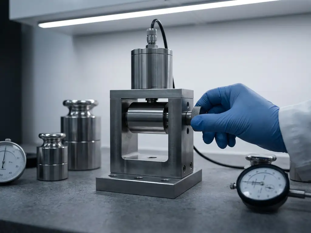
Solid-state battery (SSB) labs most commonly use spring-loaded, pneumatic, and hydraulic force test cell configurations to apply controlled stack pressure during electrochemical cycling. The choice between these configurations depends primarily on the electrolyte chemistry, the required pressure range, and whether the experiment demands constant force or constant displacement. The sections below address the most frequently asked questions about force test cell design and selection for SSB research.
Why does stack pressure matter so much in solid-state battery testing?
Stack pressure is critical in solid-state battery testing because solid electrolytes require intimate mechanical contact between electrode and electrolyte layers to maintain low interfacial resistance. Unlike liquid electrolytes, which wet electrode surfaces spontaneously, solid electrolytes cannot redistribute themselves to fill gaps created by electrode volume changes during cycling. Without adequate and well-controlled pressure, interfacial voids form, ionic resistance rises, and capacity fade accelerates.
The practical consequence is that pressure directly affects the reproducibility of electrochemical data. Two nominally identical cells cycled at different stack pressures will produce measurably different impedance spectra, different capacity retention curves, and different coulombic efficiency values. For publication-quality data, the applied force must be defined, stable, and reported alongside all other experimental parameters.
Stack pressure also influences mechanical degradation. Applying too little pressure allows delamination; applying too much can fracture brittle oxide electrolyte pellets or cause lithium metal to creep and short-circuit through sulfide electrolytes. The optimal pressure window is material-specific and often narrow, which is why dedicated force test cells with precise load control are necessary rather than simple fixed-torque assembly.
What are the main force test cell configurations used in SSB labs?
The three principal force test cell configurations found in SSB labs are spring-loaded cells, pneumatic cells, and hydraulic cells. Spring-loaded designs are the most widely deployed because they are compact, require no external infrastructure, and are straightforward to integrate into standard battery testers. Pneumatic and hydraulic configurations are preferred when precise, adjustable, or very high pressures are needed throughout an experiment.
Spring-loaded configurations
Spring-loaded force test cells use calibrated disc springs or coil springs to apply a defined compressive load to the cell stack. The spring constant determines how much the applied force changes as the electrode stack expands or contracts during cycling. Stiffer springs approximate constant-displacement conditions; softer springs allow more volume change at a relatively stable force. This configuration suits most oxide electrolyte work and many sulfide systems where pressures in the range of a few MPa are sufficient.
Pneumatic and hydraulic configurations
Pneumatic cells use regulated gas pressure acting on a piston or membrane to apply force, allowing the pressure to be adjusted in real time without disassembling the cell. Hydraulic cells operate on the same principle using incompressible fluid, which offers greater stability at very high pressures. Both configurations are particularly relevant for sulfide electrolytes, which typically require higher stack pressures, and for experiments where the researcher needs to vary pressure as an independent variable during a single cycling protocol.
What is the difference between constant-force and constant-displacement setups?
In a constant-force setup, the applied load on the cell stack remains fixed regardless of how much the electrodes expand or contract. In a constant-displacement setup, the distance between the cell’s end plates is fixed, so the force changes as the stack volume changes. The distinction matters because it determines whether the experiment controls mechanical stress or mechanical strain on the electrolyte and electrode assembly.
Constant-force configurations are better suited to studies that examine how a specific pressure level affects cycling performance, interfacial resistance, or capacity retention. Pneumatic and soft-spring cells approximate this condition. Constant-displacement configurations are more appropriate when the researcher wants to measure the force generated by electrode expansion directly, for example to characterise the mechanical behaviour of a new anode material under realistic confinement.
In practice, no spring-loaded cell is perfectly constant-force because the spring compresses or extends as the stack thickness changes. The degree of force variation depends on the spring rate and the magnitude of the thickness change. For electrodes with large volume changes, such as silicon-based anodes or lithium metal, this variation can be significant and should be accounted for in data interpretation.
How do in-situ force measurements work inside a test cell?
In-situ force measurement integrates a load cell or force sensor directly into the mechanical path of the test cell, so the compressive load on the electrode stack is recorded continuously alongside electrochemical data such as voltage, current, and impedance. The sensor is typically positioned between the current collector and the end plate, or within the piston assembly, to capture the full stack force without introducing parasitic resistance into the electrical circuit.
The signal from the force sensor is logged synchronously with the electrochemical channels of the battery tester. This allows the researcher to correlate force evolution with specific electrochemical events: the onset of lithium plating, phase transitions in the active material, or the build-up of a solid electrolyte interphase (SEI) layer on the anode. Sudden force increases during charging, for example, can indicate lithium dendrite formation before a short circuit becomes apparent in the voltage trace.
Accurate in-situ force measurement requires that the sensor is calibrated under the thermal and chemical conditions of the experiment, since temperature changes and electrolyte vapour can introduce drift. Cells designed for this purpose typically include provisions for sealing the sensor from the electrolyte environment while maintaining a direct and rigid mechanical connection to the stack.
Conventional test cells do not include a force sensor — only the initial pressure is set, and mechanical settling can reduce it over time without any indication. The PAT-Cell-Force addresses this directly by incorporating an integrated force sensor that records load continuously throughout cycling. An optional gas pressure sensor can be added to distinguish force changes caused by gas evolution from those caused by mechanical settling or electrode expansion. This is designed specifically for in-situ force monitoring in a compact format compatible with standard PAT-Series infrastructure.
Which force test cell configuration is best for oxide versus sulfide electrolytes?
Oxide electrolytes, such as garnet-type materials and NASICON-structured ceramics, are mechanically stiff and brittle. They are typically tested at moderate stack pressures, often in the range of 1 to 10 MPa, using spring-loaded force test cells. The primary concern is avoiding fracture, so configurations that provide stable, moderate, and well-defined pressure without risk of overshoot are preferred.
Sulfide electrolytes, including argyrodite and LGPS-type materials, are softer and can be cold-pressed into dense pellets at room temperature. They generally require higher stack pressures, sometimes exceeding 100 MPa during cell assembly, and benefit from pneumatic or hydraulic configurations that can sustain elevated pressures stably over long cycling periods. Sulfide cells are also sensitive to atmospheric moisture, so the force test cell must be compatible with inert-atmosphere assembly and operation.
Polymer and composite electrolytes occupy an intermediate position. They are mechanically compliant and can accommodate volume changes without fracture, but they still require sufficient pressure to maintain electrode contact, particularly at lower temperatures where polymer electrolytes stiffen. Spring-loaded cells with moderate spring rates are generally adequate, though the specific pressure requirement depends on the polymer system and the operating temperature.
What should researchers consider when selecting a force test cell for SSB work?
Selecting a force test cell for solid-state battery research requires matching the cell’s mechanical specification to the electrolyte chemistry, the electrode geometry, and the measurement objectives. The following factors are the most important to evaluate before committing to a configuration.
- Pressure range and resolution: Confirm that the cell can apply and measure forces across the full range relevant to the electrolyte system, with sufficient resolution to detect small changes during cycling.
- Force control mode: Decide whether constant-force or constant-displacement conditions are more appropriate for the experiment, and verify that the cell design supports the chosen mode.
- In-situ monitoring capability: If force evolution during cycling is a research variable, the cell must incorporate a load sensor with synchronous data acquisition rather than relying on a fixed spring assembly.
- Temperature compatibility: Many SSB experiments are conducted at elevated temperatures to improve ionic conductivity. The force test cell and its sealing components must be rated for the intended temperature range.
- Atmosphere compatibility: Sulfide electrolytes require assembly in a dry room or glove box. The cell must be sealable against moisture ingress and compatible with inert-atmosphere handling.
- Electrode area and stack geometry: The cell’s active area must match the electrode dimensions used in the study. Mismatched geometry introduces non-uniform pressure distribution, which compromises data quality.
- Compatibility with ancillary measurements: If electrochemical impedance spectroscopy (EIS), dilatometry, or optical observation are planned alongside force measurement, the cell design must accommodate those additional measurement modes without compromising mechanical integrity.
Instrument compatibility across the full experimental workflow is also a practical consideration. Using test cells, potentiostats, and data acquisition software from a single interoperable platform reduces the risk of signal synchronisation errors and simplifies data analysis. The PAT-Cell-Solid is one example of a cell designed to address the specific mechanical and electrochemical requirements of solid-state research within a standardised platform.
How EL-Cell GmbH supports force testing in solid-state battery research
We design and manufacture force test cells and supporting instrumentation specifically for the demands of solid-state battery research. Our product range addresses the full range of configurations discussed in this article, with particular attention to mechanical precision, atmosphere compatibility, and synchronous data acquisition.
Conventional test cell assembly has a notably high failure rate — studies cite figures as high as 43%. Even experienced builders achieve only around 4 out of 5 working cells, while less experienced assemblers fall below 50%. The PAT-Cell-Force and PAT-Cell-Solid from EL-CELL are designed to standardise and simplify preparation so that nearly every cell runs without failure.
Both cells use the PAT-Solid-Core insert, which features guided plane-parallel tungsten carbide plungers and a dedicated pressing tool. This ensures homogeneous compression of electrode material — something conventional cells frequently fail to achieve. The tungsten carbide plungers also withstand high mechanical loads without embedding particles or degrading over time. Conventional plungers suffer from particle embedding during use and must be ground or polished between measurements, which gradually alters cell geometry. The tungsten carbide construction eliminates this problem.
EL-CELL cells also differ from conventional designs in their sealing approach. Conventional cells typically rely on O-rings and PEEK housings; PEEK absorbs significant moisture and requires drying at 120°C under vacuum before use. EL-CELL cells instead use aluminum seals and glass-metal feedthroughs in place of O-rings, and PPS plastic in place of PEEK. PPS absorbs considerably less moisture, which reduces contamination risk and cuts preparation time.
- The PAT-Cell-Force provides continuous in-situ force monitoring during electrochemical cycling, with direct integration into the PAT-Series data acquisition ecosystem.
- The PAT-Cell-Solid is designed for solid electrolyte assemblies, with geometry and sealing options suited to both oxide and sulfide systems.
- The PAT-Cell-Press enables uniaxial pressing of solid electrolyte pellets and electrode stacks to defined pressures prior to electrochemical testing, ensuring consistent stack preparation across experiments.
- All PAT-Series cells are compatible with the PAT-Tester-i-16, which supports simultaneous electrochemical cycling, EIS, and auxiliary sensor data logging across up to 16 channels.
If you are establishing a solid-state battery testing workflow or selecting force test cell configurations for a specific electrolyte system, contact our Application Laboratory to discuss your experimental requirements and identify the most appropriate instrument combination.
Comments are closed.