


Determining the impedance of electrode materials in Lithium-Ion Batteries (LIB) and Sodium-Ion Batteries (SIB) at different states of charge (SOC) is paramount for evaluating battery performance. Especially, a reliable, artefact-free measurement of single electrode impedances at different states of charge (SOC) is a tedious endeavour since this usually involves assembling a symmetrical coin cell for each measurement at a given SOC. The alternative – measuring half-cell impedances in a three electrode setup, e.g. a PAT-Cell (Fig. 1) – is less labour intensive but usually riddled with measurement artefacts.
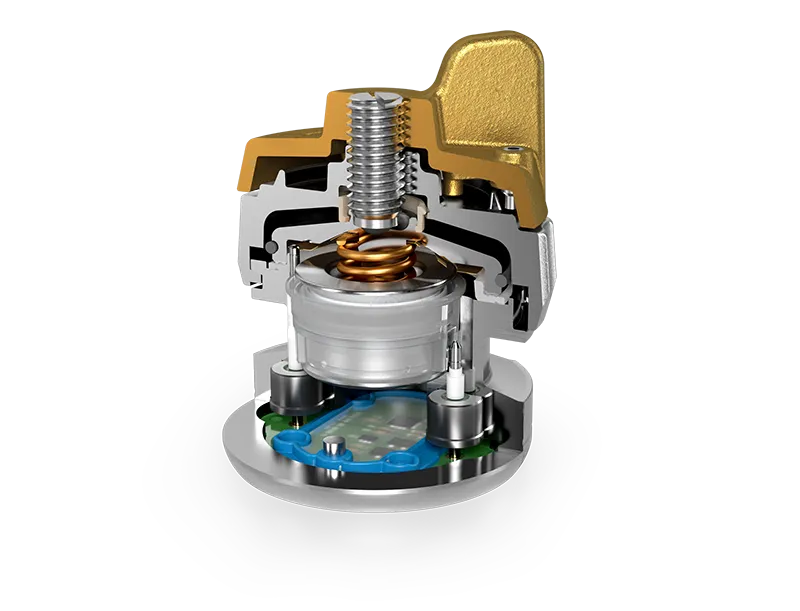
Fig. 1: PAT-Cell for three-electrode battery experiments
In this work, we present a convenient method to investigate the single electrode impedance at different SOC with only one three-electrode test cell.
The usual three-electrode setup leads to measurement artefacts
The problem:
In a conventional three-electrode test cell setup, the reference electrode (R) is typically positioned outside the cell stack, making contact through an overlapping separator. This configuration places the sensing element in a region where the current distribution is inhomogeneous, as illustrated by the bent current lines in Fig. 2.

Fig. 2: Schematic of a typical three electrode setup. The reference electrode is placed outside the cell stack and thus in a region of an inhomogeneous electrical field.
As a result, the measured potentials are erroneous. This is especially noticeable in impedance measurements, and manifests in “inductive loops” frequently observed in Nyquist plots (See Fig. 3). [1]
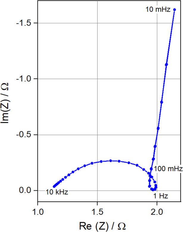
Fig. 3: Nyquist plot of the half cell impedance Z2. The measurement shows a clear measurement artifact (loop at 1 Hz).
The current density distribution at the edge of the cell stack strongly depends on the impedances of the electrodes. These impedances change with their respective SOC and thus over the course of the experiment. In conclusion, the error cannot be easily modelled and compensated for. This complicates the interpretation of the data. Consequently, half-cell impedances obtained from such three-electrode experiments are subject to significant uncertainties, rendering quantitative analysis unreliable and potentially misleading.
Triple-Decker setup reduces artefacts in half-cell impedances
The solution:
We designed an experiment with an optimised geometry: Electrode R is placed in the centre of the cell stack, between the battery electrodes 1 & 2, without an overlapping separator (See Fig. 4). This places it in a homogeneous electrical field.

Fig. 4: Schematic of the Triple Decker Setup: The reference electrode is placed in the centre of the cell stack, in a region of a homogeneous electrical field.
Electrode R, a porous, free-standing electrode of chemically partially delithiated LFP [2], was placed in an Insulation Sleeve of a PAT-Core and contacted via a stainless steel mesh with ~95 % open area. One disk of glass fibre separator was then placed on each side of electrode R. With the so prepared Insulation Sleeve, a full cell was assembled (NCM | C) and cycled in a PAT-Cell. During the CC step, GEIS measurements were performed repeatedly at different SOC. For that, a PAT-Tester-i-16 potentiostat was used.
The Result:
Nyquist plots of measured half-cell impedances of a graphite electrode in an NCM | C full cell at different SOC are depicted in Fig.5. It can be seen that the graphs are free of the typical loops usually associated with measurement artefacts. This is a clear indication that half-cell impedances obtained in the presented triple-decker configuration are much less laden with artefacts than in a conventional three-electrode setup with the sensing element placed outside the cell stack.
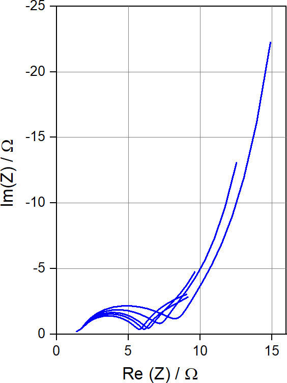
Fig. 5: Half-Cell impedances of a graphite electrode in an NCM | C full cell over various SOC, obtained in the described triple decker setup.
Conclusion:
In this work, we presented a simple and convenient method to measure both half-cell impedances of a full cell at different SOC in a single experiment. For this, we created a new sensing electrode, consisting of chemically partially delithiated LFP, that is placed in the centre of the cell stack. The experiment exploits the unique features of the PAT-Cell as a three-electrode test cell, as well as the PAT-Tester-i-16.
Literature:
[1] M. Ender et al 2017 J. Electrochem. Soc. 164 A71.
[2] Long-term Stable and Ready-to-use: Examining Partly Delithiated Lithium Iron Phosphate as Reference Material https://www.el-cell.com/lfp-reference-electrode/
_
by Dr. Bernhard E.C. Bugenhagen et al.
Related products:
3-electrode battery test cell for electrochemical testing of lithium-ion and other materials using the innovative PAT-Core concept.

Fully featured multichannel potentiostat with integrated temperature chamber.
 Reference ring, LFP, modified (10 pcs), ECC1-00-0482-C/X
About the author


Comments are closed.