


In battery research, the use of a reference electrode is a powerful tool for investigating the individual electrode potentials within a full cell. This enables a more detailed understanding and characterisation of the electrochemical mechanisms occurring at each electrode. One specific benefit is the determination of single-electrode impedances over the entire state of charge (SOC) range.
However, obtaining reliable single-electrode impedance data remains challenging. Three-electrode methods using a reference electrode are prone to producing measurement artefacts. In our previous application note, we discussed the influence of the reference ring on impedance measurements. Symmetrical two-electrode cells are considered a more reliable alternative, but they require a significant amount of experimental effort. This limits their practical application, particularly when measurements at multiple SOC values are required.
The Problem
When using ring-shaped reference electrodes in a three-electrode configuration, such as those used in the PAT-Cell from EL-Cell, pseudo-inductive measurement artefacts in the form of loops are frequently observed in the single-electrode impedance spectra (see Figure 1).
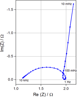
Figure 1: Nyquist plot of the graphite electrode impedance of a full cell (NCM|graphite) using a ring-shaped reference electrode. The measurement shows a clear measurement artefact (loop at 1 Hz). [1]
The underlying cause is an inhomogeneous current density distribution in the electrolyte between the anode and cathode. These inhomogeneities occur particularly at the edge of the oversized separator, exactly where the ring-shaped reference electrode measures the electrode potential. As a result, the electrode potential measured at the edge of the cell stack differs from the relevant electrode potential in the central region between the two electrodes. This voltage measurement error is transferred to the impedance. [1, 2]
Since single-electrode impedance data obtained using a reference electrode can exhibit significant measurement artefacts, symmetric cells are often used instead. To construct a symmetric cell, two identical electrodes are first brought to the same SOC in two separate cells. The electrodes must then be removed from these cells and assembled face-to-face in a new cell.
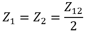
By measuring the impedance of the resulting symmetric cell, it can be assumed that both identical electrodes contribute equally to the total cell impedance. Therefore:
However, this procedure is highly time-consuming, as it must be repeated for each individual SOC. Nevertheless, the symmetric-cell approach is considered to be largely free of measurement artefacts, since the cell voltage is not significantly distorted by the inevitable current inhomogeneity at the cell edge.
The Solution: “Triple-Decker”
In this work, an alternative approach is presented, which we refer to as the “triple-decker”. For this setup, a 12 µm-thick electrode made of chemically partially delithiated LFP is coated onto a thin technical separator and electrically contacted using a fine stainless-steel mesh with 95% open area. This porous electrode (R) has the same diameter as the cathode (1) and the anode (2) and is connected as a reference electrode. Due to its small thickness and high porosity, it presents a negligible impedance to the current I12. The R electrode is insulated on both sides by additional separator layers. The resulting setup is shown on the left in Figure 2, in comparison with a conventional three-electrode setup on the right.
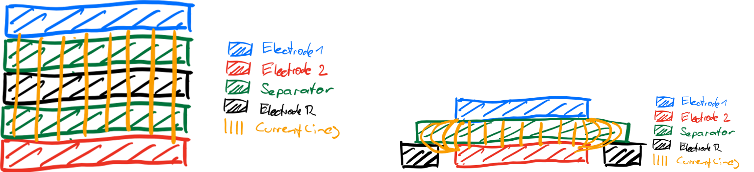
Figure 2: Schematic comparison of the triple-decker setup (left), with the reference electrode positioned centrally within a region of homogeneous electric field, and a conventional three-electrode setup (right), where the reference electrode is located outside the cell stack in a region of inhomogeneous electric field. [1]
The triple-decker design ensures a uniform current density distribution and, as a result, the electrode potentials can be measured with virtually no distortion. In addition, the reference electrode is already adjusted to a stable reference potential through the use of chemically partially delithiated LFP and can therefore be used without any further preconditioning.
Figure 3 shows the measured half-cell impedance of the investigated graphite electrode obtained using both a symmetric cell and the triple-decker cell. It can be seen directly that the impedance spectra exhibit an almost identical shape. However, the triple-decker spectra are shifted along the Re(Z) axis, which is attributable to the ohmic resistance of the additional separator layers.
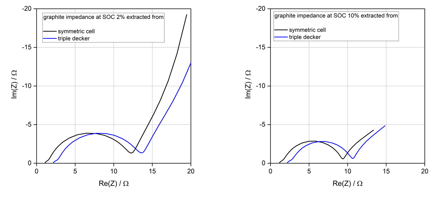
Figure 3: Half-cell impedance of graphite in symmetric and triple-decker cells at SOCs of 2% and 10%.
Conclusion
With the triple-decker setup, the impedance of individual electrodes can be conveniently characterised over the entire SOC range using a single cell, without the need to laboriously assemble and evaluate a separate symmetric cell for each SOC value. This significantly reduces experimental effort and, at the same time, minimises potential sources of error associated with disassembling and reassembling the cells.
The triple-decker therefore provides a highly attractive approach for measuring single-electrode impedance data. Compared with a ring-shaped reference electrode, the triple-decker eliminates a large proportion of the directly observable measurement artifacts. Compared with symmetric cells, the triple-decker provides comparable results while requiring significantly less experimental effort.
Outlook
We’re about to launch all the necessary components of the triple-decker. Give us a few weeks!
Literature:
[1] EL-CELL GmbH, A Comfortable Approach to Determining the Single Electrode Impedance at Varying SOC, Application Note, 2026
[2] M. Ender, J. Illig, E. Ivers-Tiffée, J. Electrochem. Soc. 164 (2017) A71–A79. https://doi.org/10.1149/2.0231702jes
–
by Jan Römer, Dr Bernhard Bugenhagen, Dr Matthias Hahn
About the author


Comments are closed.