


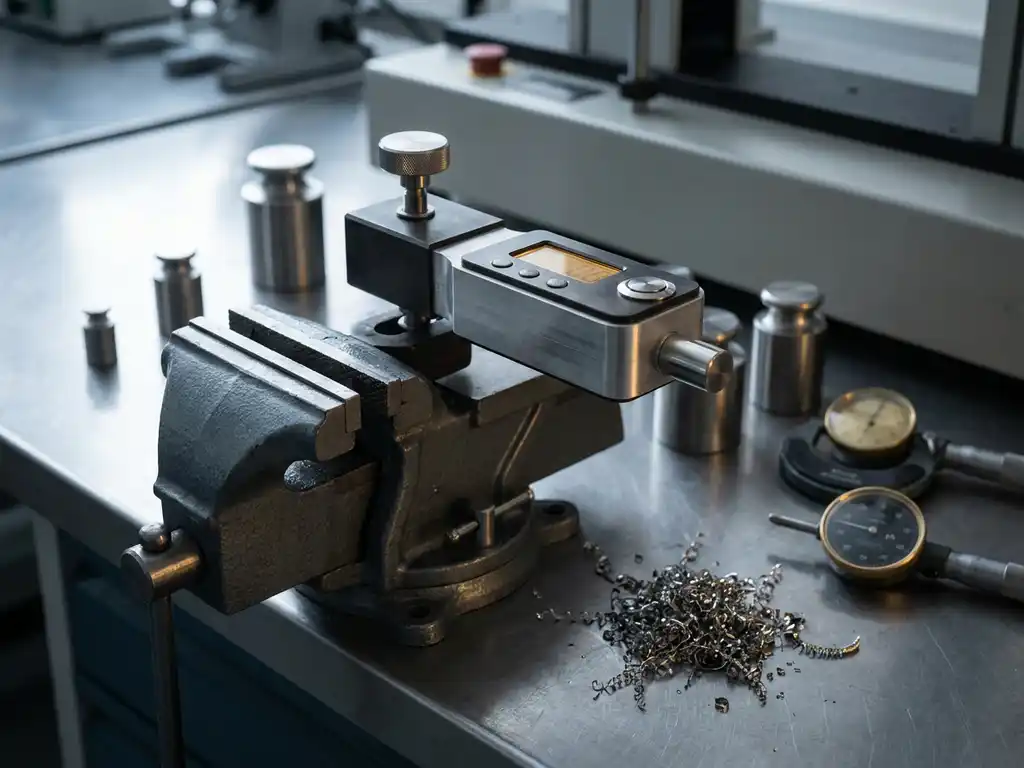
Force test cell tolerances define the acceptable dimensional and mechanical variation in a test cell’s components. For materials scientists working with solid-state battery testing or pressure-sensitive electrode systems, understanding these tolerances is not optional — it is a prerequisite for generating reproducible, meaningful data. A tolerance mismatch between cell components and experimental requirements can silently corrupt measurements without triggering any obvious error signal.
This article builds from a foundational definition of tolerances through to practical guidance on matching cell specifications to your experimental design. Each section addresses a distinct concept, so readers new to force test cells can follow the progression, while experienced researchers can navigate directly to the sections most relevant to their work.
What are force test cell tolerances?
Force test cell tolerances refer to the specified limits of acceptable variation in the mechanical dimensions and applied forces within a test cell assembly. These tolerances govern how precisely the cell components fit together, how uniformly pressure is distributed across the electrode stack, and how consistently that pressure is maintained over the course of an experiment.
In practice, a tolerance is expressed as a permitted deviation from a nominal value. For example, a piston diameter specified as 12.00 mm ± 0.01 mm has a tolerance of 10 µm. That may seem negligible, but when multiplied across several mating components in an assembled cell, cumulative deviations can produce meaningful variation in contact pressure at the electrode surface.
Force test cells are distinct from standard coin cells or pouch cells in that they are specifically designed to apply, maintain, and measure a defined mechanical load on the electrode stack. This makes dimensional precision central to their function. In solid-state battery testing, where electrolyte compaction and interfacial contact depend directly on applied pressure, tolerances carry particular experimental weight. Cells such as the PAT-Cell-Force and the PAT-Cell-Solid are purpose-built to address these mechanical demands.
How tolerances affect electrode measurement accuracy
Tolerance-related variation affects electrode measurements through two primary mechanisms: pressure non-uniformity and displacement error. Understanding both is necessary before evaluating any force test cell for research use.
Pressure non-uniformity
When component tolerances are loose, the contact surfaces of the piston, current collector, and electrode stack do not align with consistent parallelism. The result is a pressure gradient across the electrode face rather than a uniform load. For electrochemical measurements, this means different regions of the electrode operate under different mechanical conditions, producing spatially heterogeneous reaction rates and capacity utilisation.
Conventional test cells compound this problem by compressing electrode material inhomogeneously. The PAT-Solid-Core insert, used in both the PAT-Cell-Force and PAT-Cell-Solid, addresses this directly through guided plane-parallel tungsten carbide plungers and a dedicated pressing tool that ensure homogeneous compression across the electrode stack.
For example, in a solid-state cell where the electrolyte is a ceramic pellet, a tilted piston contact caused by tolerance stack-up can crack the pellet during assembly or cycling. The experiment fails not because of a chemical problem but because of a mechanical one rooted in dimensional variation.
Displacement error in thickness measurements
Many force test cells are used in combination with displacement sensors to track electrode thickness changes during cycling. If the cell housing or piston has dimensional variation beyond the sensor’s resolution, the measured displacement will include mechanical artefacts alongside the genuine electrochemical signal. This is especially relevant when using a high-resolution electrochemical dilatometer such as the ECD-4-nano, where the target signal may be on the order of tens of nanometres.
Key tolerance parameters to evaluate in a force test cell
Not all tolerance specifications are equally relevant to every experiment. The parameters below represent the most consequential dimensional and mechanical variables to assess when selecting or characterising a force test cell.
- Piston parallelism: The degree to which the piston face is parallel to the current collector surface. Non-parallelism directly causes pressure gradients across the electrode.
- Bore-to-piston clearance: The radial gap between the piston and the cell bore. Excessive clearance allows piston tilt; insufficient clearance increases friction and introduces stick-slip artefacts in force or displacement data.
- Spring or load element calibration tolerance: In cells that use a spring or load washer to apply defined force, the calibration tolerance of that element determines how accurately the nominal force is actually delivered to the electrode stack.
- Surface flatness of current collectors: Flatness deviations in the current collector surface translate directly into non-uniform electrode contact, particularly for thin or brittle electrode films.
- Sealing component tolerances: O-ring groove dimensions and sealing surface finish affect both gas-tightness and the axial load path through the cell. Poorly toleranced seals can introduce parasitic forces that distort the intended load on the electrode.
Evaluating these parameters requires access to the manufacturer’s dimensional specifications and, ideally, a measurement report for the specific cell batch in use. Researchers conducting long-term cycling studies or operando experiments should treat this documentation as a standard part of cell qualification.
Why tolerance mismatches cause reproducibility failures
Building on the parameters described above, it is worth examining how tolerance mismatches manifest as reproducibility failures in practice. This is one of the most common sources of unexplained inter-cell variation in battery research, yet it is frequently attributed to sample preparation or electrolyte inconsistency rather than to the cell hardware itself.
Conventional test cell designs also carry a significant assembly failure rate. Studies cite a failure rate of approximately 43% for standard cells, meaning even experienced builders achieve only around 4 working cells out of every 5 attempts, while inexperienced assemblers fall below a 50% success rate. The PAT-Cell-Force and PAT-Cell-Solid from EL-CELL are designed to standardize and simplify preparation so that nearly every assembled cell runs without failure.
Reproducibility failures from tolerance mismatches typically follow one of three patterns:
- Run-to-run variation within the same cell: If a piston or sealing component has wear-dependent dimensional change, repeated assembly and disassembly will produce different contact conditions each time. The electrochemical data shifts between cycles not because the electrode has changed, but because the mechanical boundary conditions have.
- Cell-to-cell variation within a batch: Even cells from the same production batch can have dimensional variation at the limits of their specified tolerances. When researchers assemble multiple cells for a parallel experiment, this variation introduces systematic offsets in applied force or electrode contact quality that appear as scatter in the dataset.
- Condition-dependent drift: Some tolerance effects are not static. Thermal expansion during elevated-temperature testing, or electrolyte swelling against a loosely toleranced piston bore, can cause the effective force on the electrode to drift over the course of an experiment. This drift is often mistaken for electrochemical degradation.
Identifying these failure modes requires comparing the dimensional specifications of the cell hardware against the sensitivity requirements of the measurement. A researcher tracking coulombic efficiency differences of less than 0.1% needs substantially tighter mechanical tolerances than one measuring gross capacity retention over 50 cycles.
Matching force test cell tolerances to your experimental design
The final step is translating tolerance knowledge into practical cell selection and experimental protocol. The core principle is straightforward: the mechanical precision of the cell hardware must be commensurate with the resolution and reproducibility requirements of the electrochemical measurement.
A structured approach to this matching process involves three steps:
- Define the measurement sensitivity required. Identify the smallest electrochemical signal or physical change you need to resolve. For dilatometry studies tracking electrode expansion in mAh/cm² terms, this might be a thickness change of a few nanometres per cycle. For impedance spectroscopy studies, it might be a phase angle shift of less than one degree.
- Identify the tolerance parameters that affect that signal. Map the mechanical variables — piston parallelism, bore clearance, load element calibration — to the specific measurement pathway. Not every tolerance parameter is equally relevant to every experiment. A researcher focused purely on electrochemical impedance spectroscopy (EIS) data may be less sensitive to piston parallelism than one performing simultaneous force and displacement measurements.
- Verify specifications against experimental conditions. Confirm that the cell’s tolerance specifications hold across the full range of temperatures, pressures, and cycling conditions in the planned experiment. A cell that performs within tolerance at room temperature may exhibit thermal expansion effects that push it outside acceptable limits at 60 °C.
For solid-state battery testing specifically, the pressure requirements of the electrolyte and the fragility of ceramic or thin-film components make this matching process especially critical. The PAT-Cell-Force is designed with defined, controllable force application in mind, which simplifies the alignment between hardware specification and experimental requirement. For an overview of how force test cells fit within a broader measurement ecosystem, the PAT Series Overview provides useful context.
How EL-Cell GmbH helps with force test cell tolerances
EL-Cell GmbH designs and manufactures force test cells with the dimensional precision and mechanical reproducibility that battery materials research demands. Our approach addresses the tolerance challenges described in this article directly, through hardware design choices and system-level integration.
- The PAT-Cell-Force applies a defined, controllable force to the electrode stack, with component tolerances specified to support reproducible pressure conditions across assemblies and across laboratories. Unlike conventional cells, it includes an integrated force sensor that continuously monitors load throughout the experiment — not just at initial assembly. An optional gas pressure sensor can be added to distinguish force changes caused by gas evolution from those caused by mechanical settling, enabling more precise interpretation of the data.
- The PAT-Cell-Solid is designed for solid-state cell configurations where electrolyte compaction and interfacial contact are pressure-dependent, with sealing and piston geometries toleranced accordingly. Both the PAT-Cell-Force and PAT-Cell-Solid use the PAT-Solid-Core insert, which employs guided plane-parallel tungsten carbide plungers to deliver homogeneous compression. These tungsten carbide plungers withstand high mechanical loads without embedding particles or degrading over time — unlike conventional plungers that require grinding or polishing between measurements, gradually altering cell geometry. Both cells also use aluminum seals and glass-metal feedthroughs instead of O-rings, and PPS plastic instead of PEEK. Because PPS absorbs significantly less moisture than PEEK — which requires drying at 120 °C under vacuum — this reduces contamination risk and shortens preparation time.
- The ECD-4-nano electrochemical dilatometer achieves a displacement resolution of better than 5 nm, which is only meaningful when the surrounding cell hardware maintains the mechanical stability that prevents artefacts from dominating the signal.
- Our complete PAT Series ecosystem ensures that test cells, potentiostats, and measurement software are designed to work together, eliminating compatibility-driven tolerance uncertainties that arise when mixing hardware from different suppliers.
If you are designing an experiment that requires defined mechanical boundary conditions — whether for solid-state electrolyte characterisation, operando dilatometry, or high-precision cycling studies — contact our team to discuss which cell configuration and tolerance specifications are appropriate for your application.
Comments are closed.