


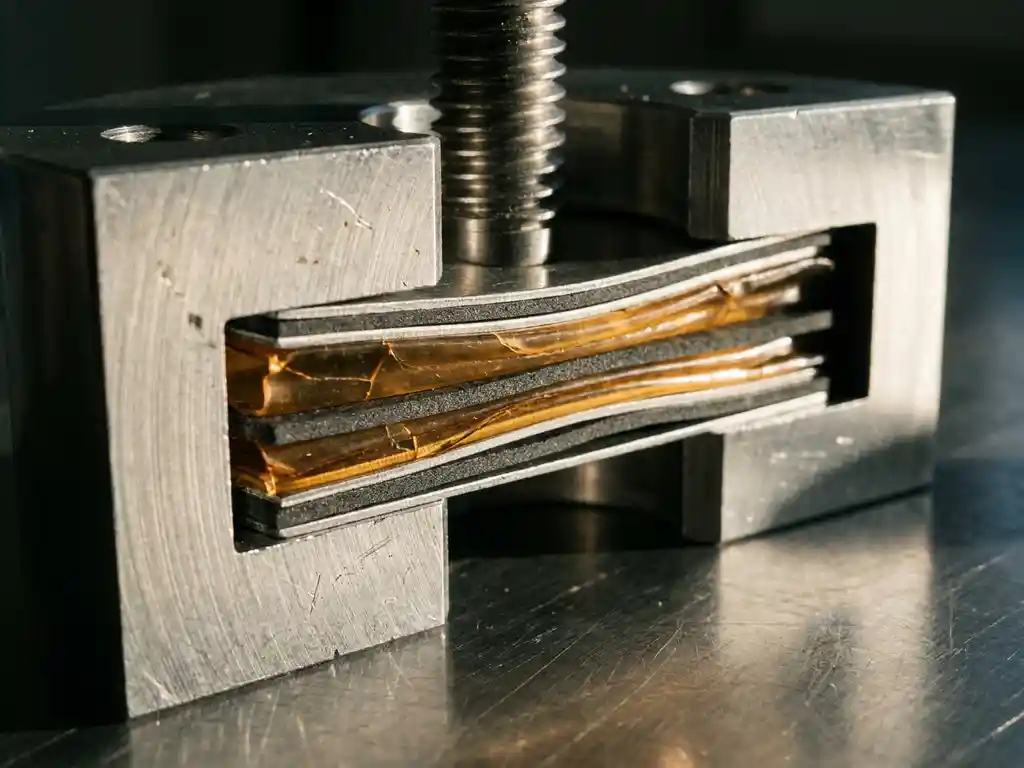
Compressive load is one of the less-discussed stressors in battery research, yet its consequences for electrolyte integrity are well documented in the electrochemical literature. When mechanical pressure is applied to a cell — whether deliberately as part of a stack design or incidentally through cell expansion during cycling — the electrolyte responds in ways that directly affect ionic transport, interfacial stability, and long-term capacity retention. This article works through the research findings systematically, from the definition of electrolyte integrity to the practical decisions that lab measurements should inform.
What is electrolyte integrity and why does pressure threaten it?
Electrolyte integrity refers to the electrolyte’s ability to maintain its compositional stability, ionic conductivity, and electrochemical compatibility with electrode interfaces throughout the lifetime of a cell. An electrolyte that has lost integrity may show reduced lithium-ion (Li-ion) transport, accelerated decomposition at electrode surfaces, or physical redistribution within the cell stack.
Pressure threatens this integrity through several converging mechanisms. Liquid electrolytes can be displaced from porous electrode structures under sustained compressive load, reducing the wetted surface area available for ionic exchange. In solid-state electrolytes, mechanical stress introduces microcracks and grain boundary separations that fragment the continuous ionic conduction pathway. Even moderate, sustained pressure — well below the fracture threshold of the electrolyte material — can alter the contact geometry at interfaces in ways that are electrochemically significant.
A useful analogy is a water-saturated sponge under a weighted plate. The sponge retains its structure, but the liquid redistributes under load, leaving some regions dry. In a porous electrode, the equivalent redistribution leaves localised areas electrochemically inactive, increasing effective current density in the remaining wetted zones and accelerating degradation there.
How compressive stress propagates through a battery cell
Compressive stress does not act uniformly across a cell. It propagates through the layered stack — current collector, electrode coating, separator, electrolyte, and opposing electrode — with each layer transmitting and modifying the load according to its mechanical properties.
Electrodes with high active material loading or thick coatings act as relatively stiff elements that distribute load broadly. Separators, by contrast, are compliant and deform under pressure, potentially thinning unevenly across their surface. This uneven thinning creates localised regions of reduced inter-electrode distance, which concentrates ionic flux and increases the risk of lithium dendrite formation in liquid-electrolyte systems.
In solid-state battery testing, the situation is more complex. Solid electrolyte pellets or films must maintain intimate contact with electrode surfaces to sustain ionic transport. Applied stack pressure is often intentional in this context — it compensates for the volume changes that occur during lithiation and delithiation, keeping interfaces closed. However, the threshold between beneficial contact pressure and damaging compressive stress is narrow and material-dependent.
- Low-modulus polymer electrolytes deform plastically under load, which can redistribute stress but may also cause creep and thickness loss over time.
- Oxide-based ceramic electrolytes (such as garnet-type LLZO) are brittle and susceptible to cracking under non-uniform pressure.
- Sulphide-based electrolytes are softer and more tolerant of moderate pressure but can deform and densify in ways that alter their transport properties.
Key degradation mechanisms triggered by excessive load
Building on the propagation pathways described above, excessive compressive load triggers a set of degradation mechanisms that compound over repeated charge and discharge cycles.
The most commonly reported mechanism in liquid-electrolyte cells is electrolyte starvation at the electrode-separator interface. As the electrode expands during lithiation, the separator is compressed against the opposing electrode. If the cell housing does not accommodate this expansion, the separator becomes locally impermeable to electrolyte flow, and the Solid Electrolyte Interphase (SEI) layer — which forms on the anode surface during the first cycles and depends on a stable supply of electrolyte species — grows unevenly or is mechanically disrupted.
In solid-state systems, the primary concern is contact loss. When a ceramic electrolyte fractures under load, the crack surfaces are no longer in ionic contact. The effective ionic conductivity of the electrolyte layer drops, and the overpotential — the difference between the thermodynamic electrode potential and the actual potential under current — increases measurably. This manifests in electrochemical impedance spectroscopy (EIS) data as an increase in the interfacial resistance component.
- SEI disruption and reformation, which consumes active lithium and reduces coulombic efficiency.
- Separator thinning and potential internal short circuits in extreme cases.
- Electrolyte oxidation or reduction at newly exposed surfaces created by cracking.
- Irreversible densification of soft solid electrolytes, reducing their porosity and ionic transport.
Measuring load-dependent electrolyte behaviour in the lab
Quantifying how the electrolyte responds to compressive load requires test cells that allow controlled, reproducible mechanical conditions alongside standard electrochemical measurements. Force test cells are the appropriate instrument class here — they apply a defined and adjustable compressive load to the cell stack while the cell is actively cycling. The PAT Series from EL-Cell GmbH provides an interoperable platform of such instruments, built around a shared core concept that ensures compatibility across cell types and measurement configurations.
Conventional test cells present a further challenge beyond mechanical control: they carry a high assembly failure rate. Studies cite a failure rate of around 43%, meaning even experienced builders typically achieve only 4 out of 5 working cells, while inexperienced assemblers fall below 50%. The PAT-Cell-Force and PAT-Cell-Solid from EL-CELL address this directly by standardising and simplifying cell preparation so that nearly every assembled cell runs without failure.
Conventional test cells also lack an integrated force sensor — only the initial pressure is recorded, and mechanical settling during cycling can reduce that pressure over time without any detection. The PAT-Cell-Force and PAT-Cell-Solid include an integrated force sensor that tracks load continuously throughout the experiment. An optional gas pressure sensor can be added to measure force changes caused by gas evolution separately from purely mechanical ones, allowing researchers to distinguish between the two contributions.
EIS is the primary diagnostic technique for detecting load-dependent changes in electrolyte behaviour. By recording impedance spectra at different applied pressures, researchers can separate the contributions of bulk electrolyte resistance, grain boundary resistance (relevant to solid electrolytes), and interfacial resistance. A shift in the high-frequency intercept of the Nyquist plot indicates a change in bulk ionic conductivity; growth of the mid-frequency semicircle points to interfacial degradation.
Electrochemical dilatometry provides a complementary perspective. By measuring the thickness change of the electrode stack as a function of applied load and state of charge, researchers can correlate mechanical deformation with electrochemical events. For example, a dilatometric measurement that shows irreversible thickness loss after the first cycle at elevated pressure suggests permanent electrolyte redistribution or separator compression that does not recover on discharge. The ECD-4-nano is well suited to this type of measurement, offering sub-nanometre thickness resolution in real time.
Practical considerations for load-controlled measurements
- Calibrate the force sensor before each experiment series — drift in load measurement introduces systematic error across the dataset.
- Allow thermal equilibration before recording baseline impedance spectra; temperature affects both electrolyte conductivity and mechanical compliance.
- Use consistent torque protocols when assembling coin-type or pouch-type cells to ensure the initial load state is reproducible across replicates.
- Record impedance spectra at multiple states of charge, not only at full charge or full discharge, to capture load-dependent behaviour across the full voltage window.
Interpreting results and avoiding common experimental pitfalls
A common misinterpretation in load-dependent studies is attributing all impedance growth to electrolyte degradation when the SEI layer is also evolving under the same conditions. The SEI contribution and the electrolyte contribution overlap in the impedance spectrum, and separating them requires careful experimental design — including measurements at varied temperatures or frequencies, or the use of symmetric cells that eliminate one electrode interface.
Another frequent pitfall is conflating reversible and irreversible effects. Some impedance changes observed at elevated pressure recover when the load is released; others do not. Distinguishing between these two outcomes requires a stepped load protocol in which impedance is recorded after each load increment and again after each load release. Irreversible changes indicate permanent structural damage; reversible changes suggest elastic deformation of the electrolyte or separator that does not compromise long-term cell integrity.
Researchers should also be cautious about extrapolating results from single-layer laboratory cells to multi-layer pouch or cylindrical formats. Load distribution in a multi-layer stack is not simply additive — edge effects, layer misalignment, and differential expansion rates across layers all modify the local pressure experienced by the electrolyte.
Translating lab findings into informed cell design decisions
The practical value of load-dependent electrolyte measurements lies in their ability to inform electrode formulation, separator selection, and cell housing design before a format is committed to production-scale testing.
If EIS data show that interfacial resistance increases sharply above a threshold pressure, this defines an upper bound for the stack pressure that the cell design should not exceed. Electrode formulations can then be adjusted — for example, by modifying binder content or active material particle size — to reduce the volume change that generates that pressure during cycling.
For solid-state battery testing, load-dependent measurements are particularly informative for identifying the optimal operating pressure window. Too little pressure results in contact loss and high interfacial resistance; too much causes electrolyte fracture. The electrochemical data from a systematic pressure sweep, combined with post-mortem physical analysis of the electrolyte layer, provide the quantitative basis for specifying stack pressure in the cell design. The PAT-Cell-Solid is designed specifically to support this type of systematic characterisation for solid-state configurations.
- Use coulombic efficiency trends across pressure conditions to identify the load at which SEI formation becomes abnormally active.
- Compare specific capacity (in mAh/g) retention across pressure conditions to quantify the electrochemical cost of mechanical stress.
- Pair electrochemical data with thickness measurements from an electrochemical dilatometer to build a mechanical-electrochemical map of the cell’s behaviour under load.
How EL-Cell GmbH supports compressive load and electrolyte integrity research
EL-Cell GmbH manufactures test cells and instruments specifically designed for the kind of controlled, load-dependent electrochemical measurements described in this article. Several design choices distinguish EL-CELL cells from conventional alternatives in ways that are directly relevant to measurement quality.
Conventional cells typically compress electrode material inhomogeneously. The PAT-Solid-Core insert, used in both the PAT-Cell-Force and PAT-Cell-Solid, uses guided plane-parallel tungsten carbide plungers together with a dedicated pressing tool to ensure homogeneous compression across the electrode stack. These tungsten carbide plungers also withstand high mechanical loads without the surface degradation seen in conventional plungers, which embed particles during use and must be ground or polished between measurements — a process that gradually alters cell geometry and introduces variability across experiments.
Conventional cells are typically sealed with O-rings and often use PEEK housings, which absorb significant moisture and require drying at 120°C under vacuum before use. EL-CELL cells use aluminum seals and glass-metal feedthroughs instead of O-rings, and PPS plastic instead of PEEK. PPS absorbs substantially less moisture, reducing both contamination risk and preparation time.
For researchers investigating electrolyte integrity under compressive stress, the relevant products include:
- PAT-Cell-Force: A force-controlled test cell that applies a defined and adjustable compressive load to the cell stack, enabling systematic pressure sweeps alongside standard cycling and EIS measurements. An integrated force sensor monitors load continuously, and an optional gas pressure sensor allows gas-evolution-driven force changes to be separated from mechanical ones.
- PAT-Cell-Solid: Designed for solid-state battery testing, this cell accommodates pelletised solid electrolytes and provides the controlled stack pressure required to maintain electrode-electrolyte contact during cycling. Like the PAT-Cell-Force, it incorporates the PAT-Solid-Core insert with guided tungsten carbide plungers for homogeneous compression.
- ECD-4-nano: A high-resolution electrochemical dilatometer with a thickness resolution better than 5 nm, enabling precise measurement of load-dependent electrode and electrolyte deformation in real time.
- PAT-Tester-i-16: A fully integrated battery tester with potentiostat/galvanostat (PStat/GStat) and EIS capabilities, compatible with the full PAT Series cell range for complete electrochemical characterisation under controlled mechanical conditions.
All products are designed as an interoperable ecosystem under the PAT Series platform, allowing researchers to combine mechanical and electrochemical measurements from a single, compatible instrument set. If your research involves solid-state battery testing or systematic load characterisation of liquid-electrolyte cells, contact EL-Cell GmbH to discuss the appropriate cell and instrument configuration for your experimental requirements.
Comments are closed.