


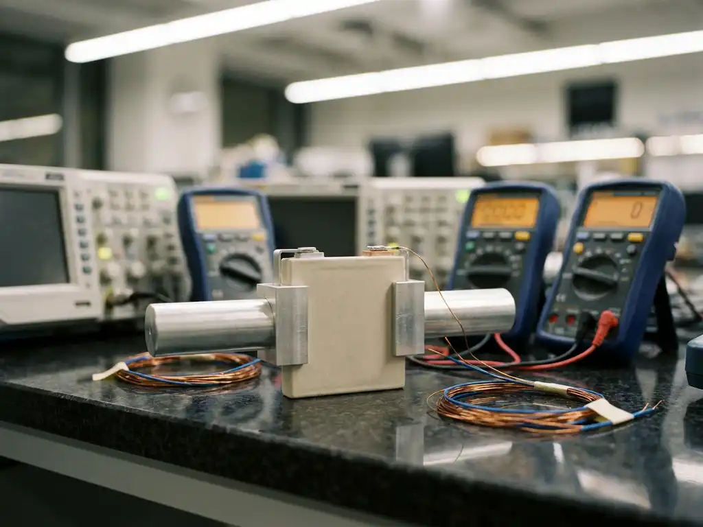
Rate capability testing for solid-state batteries measures how well a cell delivers charge and discharge capacity across a range of current densities. The test reveals how battery performance degrades as the applied current increases, which is a direct indicator of the practical power output a solid-state cell can sustain. The sections below address the most common technical questions researchers encounter when designing and interpreting rate capability experiments for solid-state systems.
How does rate capability differ in solid-state vs. liquid electrolyte batteries?
Rate capability in solid-state batteries is governed by fundamentally different transport mechanisms compared to cells using liquid electrolytes. In liquid electrolyte systems, ionic conductivity is generally high and relatively uniform throughout the electrode volume. In solid-state batteries, ion transport is constrained by the properties of the solid electrolyte and the quality of solid-solid interfaces, which introduces additional resistance that becomes especially pronounced at higher current densities.
The practical consequence is that solid-state batteries typically show steeper capacity fade as the C-rate increases. Liquid electrolyte cells can compensate for moderate ionic resistance through electrolyte infiltration into porous electrodes, whereas solid-state designs rely entirely on intimate physical contact between electrode particles and the solid electrolyte. Any gap, delamination, or interfacial resistance layer directly limits the rate at which lithium ions can move, making rate capability a particularly sensitive diagnostic for solid-state cell quality.
There is also a mechanical dimension that does not apply in the same way to liquid systems. Volume changes in the electrode during cycling can open grain boundaries or disrupt contact at the electrode-electrolyte interface, compounding resistance losses at elevated C-rates.
What is a C-rate and why does it matter for solid-state battery testing?
A C-rate is the charge or discharge current expressed as a multiple of the cell’s nominal capacity. A rate of 1C means the cell is fully charged or discharged in one hour. A rate of 0.1C corresponds to a ten-hour process, while 5C would theoretically complete the same process in twelve minutes. C-rate is the standard normalisation used in battery research because it allows direct comparison between cells of different capacities.
For solid-state battery testing, C-rate matters because the limiting mechanisms in these cells are strongly current-dependent. At low C-rates, slow interfacial kinetics and moderate ionic conductivity in the solid electrolyte may still allow near-complete lithium utilisation. As the C-rate increases, the overpotential across the solid electrolyte and at electrode-electrolyte interfaces grows, and the cell reaches its voltage cut-off before the full theoretical capacity is accessed. This capacity loss with increasing C-rate is precisely what a rate capability test quantifies.
When reporting rate capability data for solid-state cells, it is important to state whether specific capacity is given in mAh/g or mAh/cm², since electrode loading and geometry both influence how meaningful the C-rate comparison is between different experimental configurations.
How is a rate capability test typically performed on a solid-state battery?
A rate capability test is performed by cycling the cell at a series of increasing C-rates, then returning to the initial low C-rate to assess capacity recovery. The standard approach involves charging and discharging the cell at each C-rate for a fixed number of cycles, typically three to five, before stepping to the next rate. The final step at the original low C-rate confirms whether capacity loss at high rates was reversible or indicates permanent degradation.
A typical sequence might proceed as follows:
- Condition the cell at a low C-rate (commonly C/20 or C/10) for the first few formation cycles to establish stable interfaces.
- Step through increasing C-rates: for example, C/10, C/5, C/2, 1C, 2C, and 5C, recording the specific capacity at each rate.
- Return to the initial C-rate (e.g. C/10) for three to five cycles to measure capacity recovery.
- Plot specific capacity against C-rate to generate the rate capability curve.
For solid-state cells, the applied pressure on the cell stack must be controlled and recorded throughout the test. Insufficient stack pressure leads to contact loss at the solid-solid interfaces, which artificially worsens rate capability and compromises reproducibility. Temperature control is equally important, since ionic conductivity in most solid electrolytes is strongly temperature-dependent.
What factors limit rate capability in solid-state batteries?
The primary factors limiting rate capability in solid-state batteries are the ionic conductivity of the solid electrolyte, interfacial resistance at electrode-electrolyte contacts, and electronic conductivity within the composite electrode. Each of these introduces a component of overpotential that grows with increasing current, reducing the accessible capacity before the voltage cut-off is reached.
Ionic conductivity and electrolyte thickness
Even the best solid electrolyte materials have ionic conductivities that are lower than concentrated liquid electrolytes at room temperature. Thicker electrolyte layers increase the ohmic resistance proportionally, so minimising electrolyte thickness without compromising mechanical integrity is a central design challenge. Sulphide-based electrolytes generally offer higher ionic conductivity than oxide ceramics, which is reflected in their superior rate capability under comparable conditions.
Interfacial resistance and contact quality
Solid-solid interfaces between electrode particles and the electrolyte are the most common bottleneck in rate capability. Space-charge layers, chemical interdiffusion, and mechanical delamination all contribute to interfacial resistance. Coating electrode particles with ionic conductor layers or using in-situ pressure during cycling can reduce these effects, but the interfacial resistance component typically dominates the rate capability response in oxide-based solid-state cells.
Composite electrode architecture
In a composite solid-state electrode, the ratio of active material to solid electrolyte, the particle size distribution, and the mixing homogeneity all affect how uniformly current is distributed across the electrode volume. Poorly mixed electrodes show localised current concentration, which accelerates local overpotential build-up and limits the effective rate capability even when the bulk electrolyte conductivity is adequate.
What equipment is needed for rate capability testing of solid-state batteries?
Rate capability testing of solid-state batteries requires a battery cycler capable of precise galvanostatic control across a range of current densities, a test cell designed for solid-state configurations with controlled stack pressure, and a temperature-controlled environment to ensure reproducible conditions. Electrochemical impedance spectroscopy (EIS) capability is highly valuable as a complementary diagnostic to separate the contributions of bulk electrolyte resistance, interfacial resistance, and diffusion to the overall rate limitation.
The test cell is particularly critical for solid-state work. Cells must apply uniform, defined pressure to the electrode stack to maintain solid-solid contact throughout cycling. Without this, rate capability data is not reproducible between laboratories or even between experiments in the same lab. Conventional test cells present additional challenges in this regard: studies report an assembly failure rate as high as 43%, and even experienced builders achieve only around four out of five working cells, while inexperienced assemblers fall below a 50% success rate. Furthermore, conventional cells do not include a force sensor — only the initial pressure is set, and mechanical settling can reduce it over time without detection. The PAT-Cell-Force from EL-CELL addresses both issues directly. It standardises and simplifies preparation so that nearly every cell runs without failure, and it incorporates an integrated force sensor that continuously monitors stack force throughout cycling. An optional gas pressure sensor can also be added, allowing force changes caused by gas evolution to be measured separately from mechanical ones. This combination captures the full mechanical dynamics of the electrode stack alongside rate capability data.
For researchers working with solid-state battery test cells, the ability to control and monitor stack pressure independently of the electrochemical measurement is an important selection criterion. The PAT-Cell-Solid addresses this directly, providing defined and controllable stack pressure to maintain reproducible solid-solid contact throughout rate capability protocols. Like the PAT-Cell-Force, it uses the PAT-Solid-Core insert, which features guided plane-parallel tungsten carbide plungers and a dedicated pressing tool to ensure homogeneous compression of the electrode material — something conventional cells, which compress electrode material inhomogeneously, cannot reliably achieve. Both cells also replace the O-ring seals and PEEK housings common in conventional designs. PEEK absorbs significant moisture and requires drying at 120°C under vacuum; EL-CELL cells instead use aluminum seals with glass-metal feedthroughs and PPS plastic, which absorbs far less moisture, reducing both contamination risk and preparation time. The tungsten carbide plungers themselves offer a further practical advantage: unlike conventional plungers that embed particles during use and must be ground or polished between measurements — gradually altering cell geometry — tungsten carbide withstands high mechanical loads without this degradation.
How do you interpret rate capability test results for solid-state batteries?
Rate capability test results are interpreted by examining how specific capacity decreases as C-rate increases, and how much capacity is recovered when the C-rate returns to its initial value. A gradual, reversible capacity decrease with increasing C-rate indicates that kinetic limitations are the dominant factor. A steep, irreversible capacity loss suggests structural degradation, contact loss, or lithium plating at the anode interface.
Key features to examine in the rate capability curve include:
- Capacity retention at intermediate C-rates: A cell that retains most of its low-rate capacity up to 1C but drops sharply at 2C points to interfacial resistance rather than bulk electrolyte conductivity as the limiting factor.
- Voltage profiles at each C-rate: Increasing overpotential with C-rate is visible as a growing gap between charge and discharge plateau voltages. The magnitude of this polarisation indicates the total internal resistance under dynamic conditions.
- Capacity recovery at the final low C-rate step: Full recovery indicates that capacity loss at high rates was kinetic and reversible. Incomplete recovery suggests permanent structural changes, such as lithium dendrite formation or electrolyte cracking.
- Coulombic efficiency at each C-rate: Deviations from near-unity coulombic efficiency at elevated C-rates can indicate side reactions or incomplete lithium stripping and plating, particularly relevant in cells using lithium metal anodes.
Comparing rate capability data across different cells is only valid when electrode loading, active material mass, electrolyte thickness, stack pressure, and temperature are all reported and controlled. Without this information, differences in rate capability cannot be attributed to material properties with confidence.
How EL-Cell GmbH supports rate capability testing of solid-state batteries
EL-Cell GmbH designs and manufactures electrochemical test equipment specifically for battery materials research, including the instrumentation needed for rigorous rate capability testing of solid-state cells. Our product range addresses the specific requirements of solid-state testing directly:
- PAT-Cell-Solid: A test cell engineered for solid-state battery research, with defined and controllable stack pressure to maintain reproducible solid-solid contact throughout rate capability protocols. The PAT-Solid-Core insert uses guided plane-parallel tungsten carbide plungers and a dedicated pressing tool for homogeneous electrode compression, while aluminum seals, glass-metal feedthroughs, and PPS plastic minimise moisture uptake and preparation time.
- PAT-Cell-Force: Combines electrochemical cycling with an integrated force sensor, allowing researchers to correlate rate capability data with mechanical changes in the electrode stack during cycling. An optional gas pressure sensor enables separate measurement of force changes caused by gas evolution. Standardised preparation means nearly every assembled cell runs without failure.
- PAT-Tester-i-16: A multichannel battery tester with integrated galvanostatic and potentiostatic control, EIS capability, and a temperature-controlled cell chamber, providing all the measurement functions needed for a complete rate capability experiment in a single instrument.
- EL-Software: Enables the design of multi-step cycling protocols, including the stepwise C-rate sequences used in rate capability testing, with direct data export for analysis.
All instruments are designed to work together as an interoperable research ecosystem, reducing the risk of compatibility issues between the cycler, the test cell, and the data acquisition system. Researchers who need to establish a complete solid-state testing workflow can contact us directly to discuss their experimental requirements and identify the most appropriate configuration for their laboratory.
Comments are closed.