


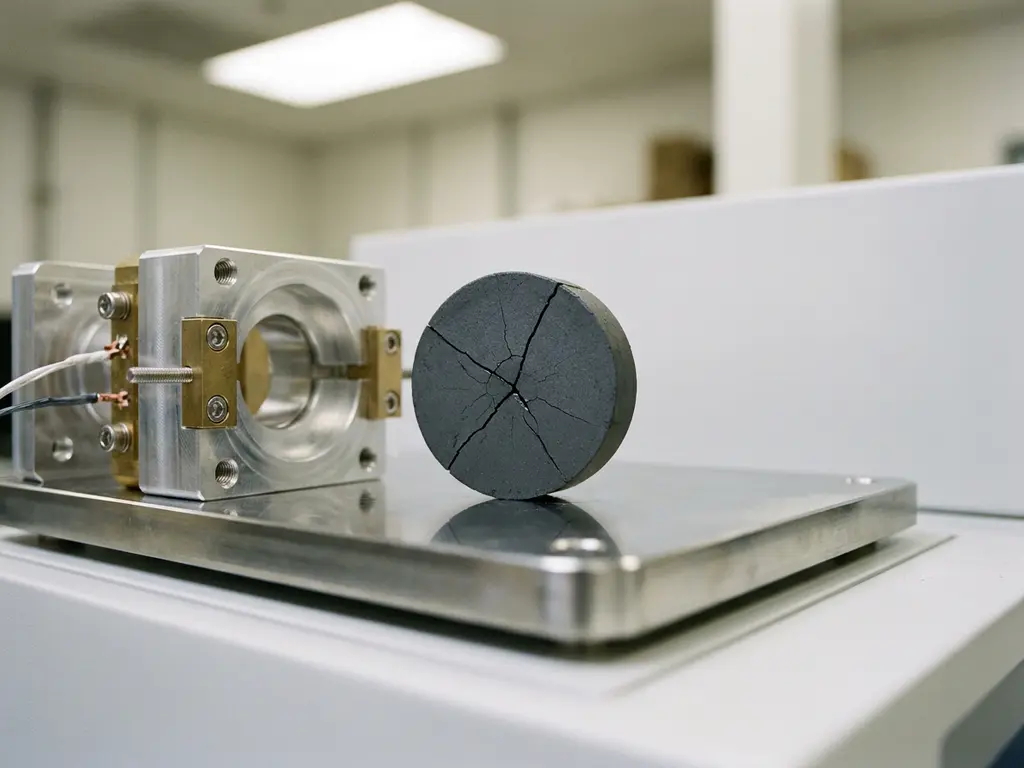
Solid-state batteries fail during testing primarily due to mechanical stress, interfacial instability, and lithium dendrite formation. Unlike liquid-electrolyte cells, solid-state designs cannot accommodate volume changes or interface degradation through electrolyte redistribution, making them far more sensitive to the conditions imposed during electrochemical cycling. The sections below address the specific failure mechanisms researchers encounter most frequently.
What are the most common failure mechanisms in solid-state batteries?
Solid-state battery failure during testing typically originates from four interconnected mechanisms: interfacial delamination between electrode and electrolyte layers, lithium dendrite penetration through the solid electrolyte, mechanical fracture of brittle electrolyte materials, and ionic conductivity degradation at grain boundaries. Each mechanism can occur independently or compound with others, making diagnosis challenging without systematic characterisation.
The rigid structure of solid electrolytes is both their advantage and their vulnerability. During charge and discharge, electrode materials expand and contract. In a liquid-electrolyte cell, the electrolyte simply wets the electrode surface and maintains ionic contact throughout. In a solid-state cell, that same volume change creates mechanical stress at the interface, and repeated cycling gradually opens gaps that interrupt ionic transport.
- Interfacial delamination: Loss of physical contact between electrode and electrolyte, increasing interfacial resistance
- Dendrite penetration: Lithium filaments propagating through grain boundaries or defects in the electrolyte
- Electrolyte fracture: Brittle cracking of oxide or sulphide electrolytes under cyclic stress
- Grain boundary degradation: Reduced ionic conductivity at polycrystalline interfaces, particularly at elevated temperatures
- Chemical side reactions: Decomposition of the electrolyte at the electrode interface, forming resistive secondary phases
Understanding which mechanism dominates in a given cell design requires a combination of electrochemical impedance spectroscopy (EIS), mechanical monitoring, and post-mortem analysis.
Why does the solid electrolyte interface cause testing problems?
The solid electrolyte interface in solid-state batteries creates testing problems because it is chemically and mechanically unstable under the conditions required for cell operation. Unlike the solid electrolyte interphase (SEI) layer that forms on anodes in liquid-electrolyte cells during early cycles, the electrode-electrolyte interface in solid-state systems is a fixed solid-solid contact that cannot self-heal or redistribute when degraded.
Chemical incompatibility between electrode materials and the solid electrolyte is a well-documented challenge. Sulphide-based electrolytes, which offer high ionic conductivity, are particularly prone to oxidation at the cathode interface and reduction at the lithium anode. These reactions produce ionically resistive secondary phases that grow with each cycle, progressively increasing overpotential and reducing accessible capacity.
From a testing perspective, this manifests as a gradual rise in interfacial resistance visible in EIS spectra, combined with declining coulombic efficiency and increasing voltage polarisation. Distinguishing interfacial resistance from bulk electrolyte resistance requires careful impedance analysis across multiple frequencies, and this separation becomes increasingly difficult as the cell ages.
Oxide electrolytes such as garnet-type materials are more chemically stable but introduce a different problem: their high stiffness makes intimate contact with electrode particles difficult to achieve and maintain. Even small gaps at the interface create high local current densities, which accelerate both dendrite nucleation and further delamination.
How does mechanical stress during cycling lead to cell failure?
Mechanical stress during cycling leads to solid-state cell failure because electrode volume changes generate forces that solid electrolyte materials cannot absorb without fracturing or losing contact with the electrode. Silicon and lithium metal anodes are particularly problematic, with volume expansions that can exceed 100% and 0% respectively for lithium, but with significant local stress concentrations at grain boundaries and contact points.
Each charge-discharge cycle imposes a fatigue load on the electrolyte. Oxide electrolytes, being ceramics, are brittle and will eventually crack under repeated strain. Sulphide electrolytes are softer and more deformable, but they can undergo plastic deformation that permanently alters the geometry of the electrolyte layer, creating regions of uneven current distribution.
Applied stack pressure is one of the primary variables researchers use to manage this problem. Insufficient pressure allows voids to form at the electrode-electrolyte interface, increasing resistance. Excessive pressure can fracture the electrolyte or cause lithium extrusion. Finding the correct pressure window for a given cell design is therefore a critical part of the testing protocol, and it must be maintained consistently throughout cycling.
A further complication with conventional test cells is that they do not include a force sensor — only the initial pressure is set, and mechanical settling can reduce it over time without any indication to the researcher. The PAT-Cell-Force from EL-CELL addresses this directly with an integrated force sensor. An optional gas pressure sensor can also be added, allowing force changes caused by gas evolution to be measured separately from purely mechanical ones, which is particularly valuable when diagnosing failure in cells where gassing and mechanical degradation may occur simultaneously.
Monitoring electrode thickness changes during cycling provides direct evidence of mechanical stress accumulation. Dilatometry measurements correlate volume changes with electrochemical state, allowing researchers to identify cycles where irreversible deformation begins and to link those events to changes in impedance or capacity. The ECD-4-nano electrochemical dilatometer is designed for precisely this purpose, offering sub-5 nm displacement resolution for high-precision volume change quantification.
What causes lithium dendrite growth in solid-state batteries?
Lithium dendrite growth in solid-state batteries is caused by non-uniform current distribution at the lithium metal anode surface, which drives localised lithium deposition into grain boundaries, pores, or defects within the solid electrolyte. Contrary to early expectations, solid electrolytes do not inherently prevent dendrite formation; under sufficiently high current densities, dendrites can propagate through even dense electrolyte layers.
The critical current density (CCD) is the threshold above which dendrite nucleation becomes thermodynamically favourable at a given interface. Below the CCD, lithium plates relatively uniformly; above it, filament growth initiates. The CCD depends on electrolyte type, temperature, stack pressure, and interfacial quality. In research settings, determining the CCD for a specific electrolyte-electrode combination is a standard characterisation step.
Grain boundaries in polycrystalline electrolytes are preferential pathways for dendrite propagation because they present lower mechanical resistance and often contain higher concentrations of defects or impurities. Single-crystal electrolytes reduce this risk but introduce manufacturing complexity. Amorphous electrolytes eliminate grain boundaries entirely but typically exhibit lower ionic conductivity.
From a testing standpoint, dendrite formation is often detected as a sudden internal short circuit, characterised by a voltage drop to near zero during charging. Post-mortem cross-sectional analysis is required to confirm dendrite penetration and identify the propagation pathway. EIS performed at regular intervals during cycling can sometimes detect early-stage dendrite growth as an anomalous decrease in electrolyte resistance before a full short circuit occurs.
How does temperature affect solid-state battery performance in testing?
Temperature significantly affects solid-state battery performance in testing because ionic conductivity in solid electrolytes is strongly temperature-dependent, and thermal gradients within the cell can create non-uniform current distributions that accelerate failure. Most solid electrolytes exhibit substantially lower ionic conductivity at room temperature compared to liquid electrolytes, making temperature control a critical experimental variable.
Sulphide electrolytes generally perform well near room temperature but are sensitive to humidity and can undergo phase transitions at elevated temperatures that alter their conductivity. Oxide electrolytes typically require elevated operating temperatures to achieve adequate ionic conductivity, which introduces additional complexity in test cell design and sealing.
Temperature also affects the mechanical properties of the electrolyte. At lower temperatures, electrolytes become more brittle and the risk of fracture under cycling stress increases. At elevated temperatures, some materials soften, which can improve contact but may also promote unwanted chemical reactions at the electrode-electrolyte interface.
For reproducible testing, maintaining a stable and uniform temperature throughout the cell is essential. Temperature gradients across the cell stack can create differential expansion rates and localised stress concentrations, which compromise both the mechanical integrity of the cell and the validity of electrochemical measurements. Controlled-temperature cell chambers that maintain uniform thermal conditions are therefore a practical requirement for solid-state battery research, not an optional accessory.
What test equipment features help diagnose solid-state battery failures?
Diagnosing solid-state battery failure mechanisms requires test equipment capable of combining precise electrochemical measurement with mechanical monitoring and controlled environmental conditions. The most informative diagnostic tools integrate EIS with galvanostatic cycling, apply defined stack pressure, monitor electrode thickness changes, and maintain stable temperature throughout the experiment.
Electrochemical impedance spectroscopy for failure analysis
EIS is the primary tool for separating bulk electrolyte resistance, interfacial resistance, and charge-transfer resistance within a solid-state cell. By fitting impedance spectra to equivalent circuit models, researchers can track how each resistance component evolves with cycling and identify which interface is degrading. Performing EIS at multiple temperatures adds further diagnostic resolution, as different processes have distinct activation energies.
For solid-state cells, EIS measurements must be performed under the same stack pressure as the cycling experiment, as pressure changes alter interfacial contact and therefore impedance. Any test platform used for solid-state research should allow EIS to be performed in situ, without disassembling or disturbing the cell.
Mechanical monitoring and pressure control
Monitoring electrode thickness changes during cycling provides a direct measure of mechanical stress accumulation and volume change behaviour. High-resolution dilatometry, with sub-micrometre displacement resolution, can detect the onset of irreversible deformation before it manifests as a measurable change in electrochemical performance. The PAT-Cell-Force is designed specifically for this application, combining defined uniaxial stack pressure with in-situ thickness measurement in a format compatible with standard electrochemical cycling protocols.
Controlled stack pressure is equally important. A test cell that cannot apply and maintain a defined, reproducible pressure throughout cycling will produce data that cannot be reliably compared between experiments or between laboratories. This is a basic requirement for any solid-state battery testing programme.
Conventional test cells also present a significant challenge at the assembly stage. Studies cite an assembly failure rate of around 43% for conventional designs, and even experienced builders typically achieve only four out of five working cells. Inexperienced researchers fall below a 50% success rate. The PAT-Cell-Force and PAT-Cell-Solid from EL-CELL are designed to address this directly: standardised preparation procedures and the PAT-Solid-Core insert simplify assembly to the point where nearly every cell runs without failure.
The PAT-Solid-Core insert, used in both the PAT-Cell-Force and PAT-Cell-Solid, uses guided plane-parallel tungsten carbide plungers and a dedicated pressing tool to ensure homogeneous compression of electrode material. Conventional cells compress electrode material inhomogeneously, which introduces variability that is difficult to distinguish from genuine electrochemical effects. The tungsten carbide plungers also withstand high mechanical loads without embedding particles or degrading over time — a known problem with conventional plungers, which must be ground or polished between measurements, gradually altering cell geometry.
Sealing is another area where conventional cells introduce contamination risk. Most conventional cells rely on O-rings and PEEK housings; PEEK absorbs significant moisture and requires drying at 120°C under vacuum before use. EL-CELL cells use aluminum seals and glass-metal feedthroughs instead of O-rings, and PPS plastic instead of PEEK. PPS absorbs substantially less moisture, reducing both contamination risk and the preparation time needed before cells can be assembled.
Controlled temperature environments
A temperature-controlled cell chamber eliminates thermal gradients and allows systematic investigation of temperature-dependent behaviour. Instruments that integrate the cell chamber with the potentiostat and galvanostat reduce cabling complexity and improve measurement accuracy by minimising lead resistance and electromagnetic interference. The PAT-Tester-i-16 combines a 16-channel battery tester with a temperature-controlled chamber and EIS capability in a single instrument, which is particularly useful when running multiple solid-state cells in parallel under identical conditions.
How EL-Cell GmbH supports solid-state battery failure analysis
EL-Cell GmbH designs and manufactures test equipment specifically for the experimental demands of solid-state battery research. Our product range addresses the core requirements for rigorous failure analysis: controlled stack pressure, in-situ mechanical monitoring, high-resolution EIS, and stable temperature management.
- The PAT-Cell-Solid is a dedicated test cell for solid-state battery research, designed to apply defined uniaxial pressure to pelletised solid electrolyte stacks while maintaining a hermetically sealed environment
- The PAT-Cell-Force combines pressure control with in-situ thickness measurement, enabling simultaneous electrochemical and mechanical characterisation throughout cycling
- The ECD-4-nano electrochemical dilatometer provides sub-5 nm displacement resolution for quantifying electrode volume changes with high precision
- The PAT-Tester-i-16 integrates cycling, EIS, and temperature control into a single instrument, supporting up to 16 channels for parallel solid-state cell testing
- All products are designed as an interoperable ecosystem under the PAT Series platform, ensuring compatibility between test cells, testers, and EL-Software for streamlined data acquisition and analysis
If you are developing a solid-state battery testing protocol or need to diagnose specific failure mechanisms in your cell design, contact us to discuss which combination of instruments best suits your experimental requirements.
Comments are closed.