


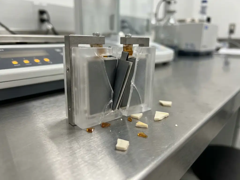
Conventional test fixtures designed for liquid-electrolyte cells introduce systematic errors when applied to solid-state battery research. The root cause is straightforward: solid-state cells operate under fundamentally different physical and electrochemical conditions, and hardware that ignores those differences produces data that cannot be trusted. This article works through the core reasons why, starting with what makes solid-state cells mechanically and electrochemically distinct, then examining how standard fixtures fail to accommodate those differences, and finally outlining what purpose-built hardware controls instead.
What Makes Solid-State Batteries Fundamentally Different to Test
Solid-state batteries replace the liquid or gel electrolyte found in conventional lithium-ion cells with a solid ionic conductor. This single change has cascading consequences for how the cell must be assembled, constrained, and measured.
In a liquid-electrolyte cell, the electrolyte wets electrode surfaces spontaneously, filling pores and conforming to surface irregularities. Ionic contact is established by the liquid itself. In a solid-state cell, ionic contact between the electrolyte and electrode layers depends entirely on physical pressure and surface quality. There is no wetting mechanism to compensate for imperfect interfaces.
This has direct implications for testing. The interfacial resistance between a solid electrolyte and an electrode is highly sensitive to the applied stack pressure. A cell tested at insufficient pressure will show elevated impedance and reduced capacity that reflect the poor interface, not the intrinsic material properties. Conversely, excessive or uneven pressure can fracture brittle ceramic electrolytes such as oxide-based garnets or LLZO. The measurement window for meaningful data is narrow and pressure-dependent.
- Solid electrolytes are mechanically brittle and fracture under uneven or excessive load
- Ionic contact is pressure-dependent, not self-establishing as with liquid electrolytes
- Electrode volume changes during cycling create dynamic stack pressure variations
- Many solid electrolytes are moisture-sensitive and require assembly in an inert or dry atmosphere
How Conventional Test Fixtures Were Designed — and for What
Standard coin cells and cylindrical test fixtures were engineered around the physical properties of liquid electrolytes. Their design priorities reflect that origin and are not incidental limitations.
Coin cell hardware, for example, uses a spring-loaded crimp closure to apply a compressive force that holds the stack together. The force is determined by the spring constant and the degree of crimping, neither of which is calibrated or adjustable during the experiment. For liquid-electrolyte cells, this is adequate because the electrolyte fills any gaps and maintains ionic contact regardless of minor pressure variation. The spring provides enough force to prevent the stack from separating, and that is sufficient.
Conventional fixtures also rely on the liquid electrolyte to act as a sealing medium of sorts, filling internal voids and preventing short circuits through physical contact alone. Sealing requirements are modest because the electrolyte is already contained within the crimp. Temperature control is typically external and approximate. Electrochemical impedance spectroscopy (EIS) measurements made in these fixtures carry contributions from the fixture geometry and contact resistance, but these are generally small relative to the liquid-electrolyte cell impedance and can often be subtracted or ignored.
Beyond these measurement limitations, conventional test cells also suffer from a high assembly failure rate. Studies cite a failure rate of around 43%, meaning even experienced builders typically achieve only 4 out of every 5 working cells, while inexperienced assemblers fall below a 50% success rate. This unreliability compounds the data quality problems already introduced by uncontrolled pressure and inadequate sealing.
The result is hardware that works well for its intended purpose but embeds assumptions that are violated by every aspect of solid-state cell behaviour.
Why Pressure, Contact, and Sealing Conditions Distort Solid-State Data
When a conventional fixture is used for solid-state battery testing, three specific failure modes introduce systematic errors into the data.
Uncontrolled and non-uniform stack pressure
A coin cell spring applies a nominal force, but that force is not measured, not uniform across the electrode area, and not maintained at a defined value as the cell cycles and electrode thickness changes. Conventional cells do not include a force sensor — only the initial pressure is set, and mechanical settling can reduce it over time without detection. For a solid-state cell, this means the interfacial resistance between the electrolyte and electrodes will drift throughout the experiment in ways that are unrelated to the electrochemical processes under study. Capacity fade, overpotential increases, and impedance growth that appear in the data may be artefacts of changing contact conditions rather than material degradation.
Inadequate contact area control
Solid electrolyte pellets and thin-film stacks require planar, parallel contact surfaces applying uniform pressure. Conventional fixtures do not guarantee this, and their plungers compress electrode material inhomogeneously. Tilted or non-parallel contact produces edge loading, which concentrates stress at the electrolyte perimeter and creates a gradient of ionic contact quality across the electrode area. Current distribution becomes non-uniform, and the measured electrochemical response is an average of regions with very different local conditions. Compounding this, conventional plungers embed particles during use and must be ground or polished between measurements, which gradually alters the cell geometry over time.
Sealing incompatibility with sensitive electrolytes
Sulphide-based solid electrolytes react with moisture and oxygen at concentrations that conventional fixture sealing cannot exclude. Even brief atmospheric exposure during assembly or cycling can alter the electrolyte chemistry and introduce artefacts into electrochemical impedance spectroscopy (EIS) spectra and capacity measurements. Conventional fixtures designed for liquid electrolytes typically seal with O-rings and use PEEK housings, which absorb significant moisture and require drying at 120°C under vacuum — adding preparation time and contamination risk. These designs do not provide the hermetic sealing required for moisture-sensitive solid electrolyte materials.
What Purpose-Built Solid-State Test Cells Control Differently
Purpose-built force test cells address these failure modes by replacing assumptions with controlled, measurable parameters. The design philosophy shifts from “adequate for liquid cells” to “defined conditions for solid-state cells.”
The most fundamental difference is active stack pressure control. A force test cell incorporates a calibrated spring, a load cell, or an external pressure application system that allows the researcher to set and monitor the pressure applied to the electrode stack throughout the experiment. This means interfacial resistance changes observed in EIS data can be attributed to electrochemical processes rather than mechanical drift.
- Defined, reproducible stack pressure applied via a calibrated spring or external load
- Parallel, planar contact surfaces ensuring uniform current distribution
- Hermetic sealing compatible with moisture-sensitive sulphide and halide electrolytes
- Rigid cell body that prevents stack expansion from relieving applied pressure unpredictably
- Compatible geometry for in-situ EIS and dilatometry measurements during cycling
A rigid cell body is equally important. When electrodes expand during lithiation, a compliant fixture allows the stack to push the contacts apart, reducing pressure and contact quality. A rigid body with a defined pressure mechanism converts electrode expansion into a measurable force change rather than uncontrolled gap formation. This makes the mechanical data interpretable alongside the electrochemical data.
Matching the Right Cell Configuration to Your Solid-State Experiment
Building on the pressure and contact principles established above, the practical question for researchers is how to select a cell configuration that matches the specific demands of their solid-state experiment. Not all solid-state chemistries or research questions require the same hardware.
Oxide versus sulphide electrolytes
Oxide-based electrolytes such as LLZO garnets are mechanically robust but require high sintering pressures to achieve dense pellets. Once sintered, they can tolerate assembly in moderately controlled atmospheres. Sulphide-based electrolytes, including LGPS and argyrodite-family materials, are more ionically conductive but highly sensitive to moisture and require assembly and testing under inert gas or dry room conditions. The sealing standard of the test cell must match the atmospheric sensitivity of the electrolyte, not simply the convenience of the researcher.
Half-cell versus full-cell configurations
Half-cell configurations using a lithium metal counter electrode are common in early-stage material screening because they decouple cathode and electrolyte contributions to the measured response. However, lithium metal is highly reactive and creeps under pressure, meaning the applied stack force changes the lithium morphology and interface over time. Full-cell configurations eliminate the lithium metal reference artefact but require careful balancing of anode and cathode capacities to avoid lithium plating or electrolyte decomposition at the extremes of the voltage window.
In-situ and operando measurement requirements
If the experiment requires simultaneous EIS, dilatometry, or optical access during cycling, the cell configuration must be selected with those measurement modalities in mind from the outset. Retrofitting in-situ capability to a standard fixture typically compromises either the measurement quality or the cell integrity. Selecting a cell platform designed for operando access — with optical windows, displacement sensor ports, or integrated reference electrode channels — is more reliable than adapting hardware not designed for that purpose.
How EL-Cell GmbH Supports Solid-State Battery Testing
EL-Cell GmbH designs and manufactures test cells and instrumentation specifically for the conditions that solid-state battery research demands. Our product range addresses the pressure control, sealing, and measurement integration requirements described throughout this article. The PAT-Cell-Force and PAT-Cell-Solid are designed to standardize and simplify cell preparation so that nearly every cell runs without failure — directly countering the high assembly failure rates associated with conventional test cells.
- The PAT-Cell-Force applies defined, reproducible stack pressure via a calibrated spring mechanism, enabling controlled interfacial contact for solid electrolyte pellets and thin-film stacks. It includes an integrated force sensor that continuously monitors stack pressure throughout the experiment, and an optional gas pressure sensor can be added to distinguish force changes caused by gas evolution from purely mechanical ones.
- The PAT-Cell-Solid is designed specifically for solid-state cell assembly and testing, with hermetic sealing suitable for moisture-sensitive sulphide and halide electrolytes. Like the PAT-Cell-Force, it also incorporates an integrated force sensor for real-time pressure monitoring.
- Both the PAT-Cell-Force and PAT-Cell-Solid use the PAT-Solid-Core insert, which features guided plane-parallel tungsten carbide plungers and a dedicated pressing tool to ensure homogeneous compression of electrode material. The tungsten carbide plungers withstand high mechanical loads without embedding particles or degrading, eliminating the need for grinding or polishing between measurements and preserving cell geometry over time.
- Both cells use aluminum seals and glass-metal feedthroughs instead of O-rings, and PPS plastic instead of PEEK. PPS absorbs significantly less moisture than PEEK, reducing contamination risk and cutting preparation time by removing the need for high-temperature vacuum drying.
- The PAT-Cell-Press II provides externally applied uniaxial pressure, allowing researchers to vary and monitor stack force independently of cell geometry during cycling experiments.
- The ECD-4-nano electrochemical dilatometer enables simultaneous thickness change measurement with sub-5 nm resolution alongside electrochemical cycling, supporting operando characterisation of electrode and electrolyte layer mechanics.
- All PAT Series cells are compatible with the PAT-Tester-i-16, which integrates galvanostatic and potentiostatic cycling with EIS capability in a single temperature-controlled instrument.
If you are designing a solid-state testing protocol or selecting hardware for a new research programme, we are glad to discuss which cell configuration best matches your electrolyte chemistry and experimental requirements. Contact us directly to speak with our application specialists.
Comments are closed.