


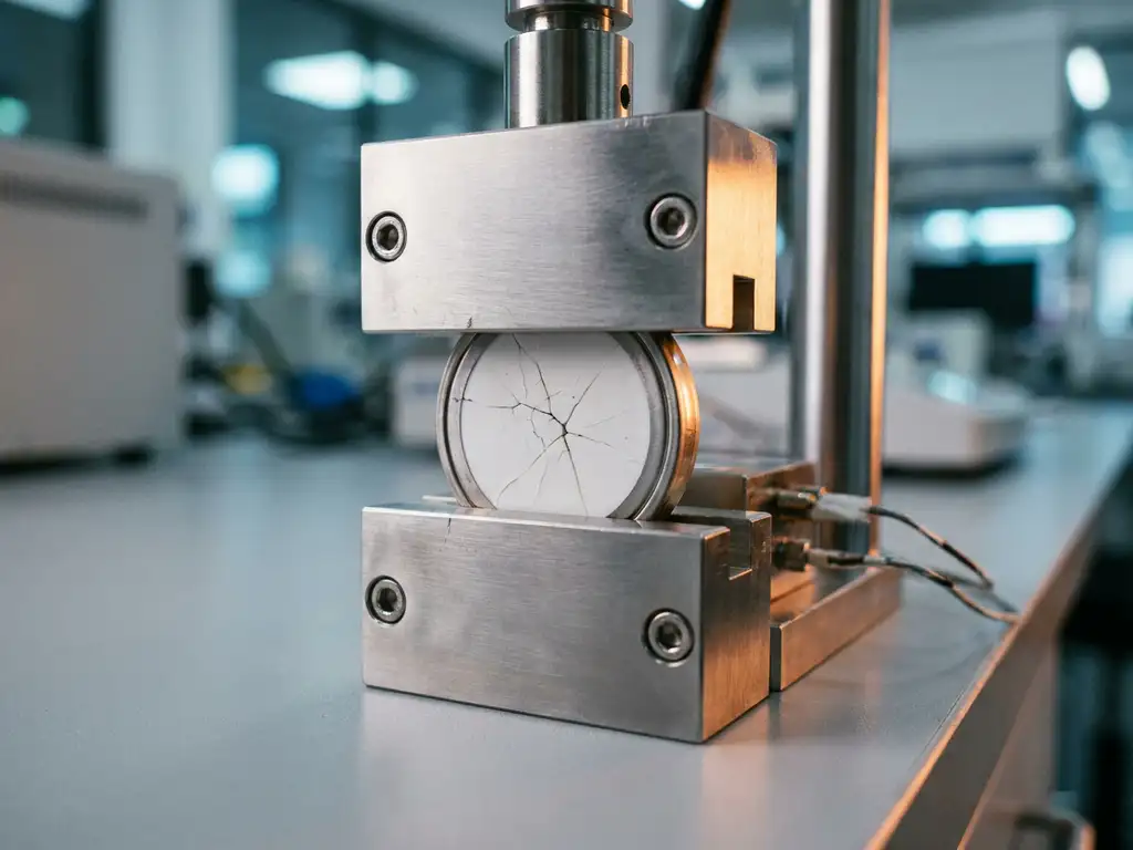
Force test cells reveal hidden failure modes in solid-state batteries by measuring the mechanical forces that develop inside a cell during cycling — forces that electrochemical data alone cannot capture. In solid-state batteries, where a rigid ceramic or polymer electrolyte replaces the liquid electrolyte found in conventional lithium-ion cells, mechanical stress is not a secondary concern. It is frequently the primary driver of capacity fade, internal short circuits, and premature cell death. This article builds from the fundamentals of force measurement through to practical experimental design and data interpretation, giving researchers a structured framework for incorporating mechanical characterisation into solid-state battery research.
What are force test cells and how do they work?
A force test cell is a battery test cell equipped with an integrated load sensor that continuously measures the compressive or tensile force acting across the electrode stack during electrochemical cycling. Unlike conventional test cells, which provide only voltage, current, and capacity data, force test cells add a mechanical dimension to every measurement.
The operating principle is straightforward. As a battery charges and discharges, electrode materials expand and contract. In a constrained cell geometry — where the stack cannot freely swell — these dimensional changes translate directly into measurable force variations. The load sensor records these variations in real time, synchronised with the electrochemical data from the potentiostat or galvanostat.
For example, when a graphite anode lithiates during charging, it expands by roughly ten per cent in volume. In a rigid housing, this expansion produces a measurable compressive force. A force test cell captures this signal continuously, producing a force curve that runs in parallel with the charge/discharge profile. In solid-state batteries, where the electrolyte itself is a structural component, these force signals carry substantially more diagnostic information than they do in liquid-electrolyte systems. Researchers looking for an introduction to the broader platform context may find the PAT Series Overview a useful starting point.
- Integrated load sensor: positioned within the cell stack to measure in-plane or through-plane force
- Synchronised data acquisition: force data is time-stamped alongside voltage and current from the test instrument
- Constrained geometry: the cell housing prevents free expansion, converting dimensional change into a measurable force signal
- Configurable stack pressure: applied pre-load can be set to replicate conditions relevant to the intended application
How mechanical stress drives failure in solid-state batteries
In liquid-electrolyte lithium-ion cells, the electrolyte accommodates small electrode movements by flowing around particle surfaces. Solid electrolytes cannot do this. Every dimensional change in the electrode must be accommodated by the surrounding solid material, and when that accommodation fails, the consequences are structural.
The core problem is a mismatch in mechanical properties. Electrode active materials — particularly high-capacity anodes such as silicon or lithium metal, and layered oxide cathodes — undergo significant volume changes during lithiation and delithiation. The solid electrolyte, whether an oxide ceramic, sulphide glass-ceramic, or polymer composite, has its own stiffness and fracture toughness. When the strain energy at the electrode-electrolyte interface exceeds the fracture energy of the electrolyte, cracking begins.
Cracking is not simply a structural inconvenience. Each new crack surface exposes fresh electrolyte material to reactive electrode surfaces, consuming lithium and increasing interfacial resistance. Repeated cracking and healing cycles progressively degrade ionic contact across the interface. In severe cases, crack propagation provides a conductive pathway for lithium dendrite growth, leading to internal short circuits.
Building on this, it is important to recognise that stress does not act uniformly across the cell. Local stress concentrations develop at grain boundaries, at electrode particle contacts, and in regions of non-uniform current distribution. These localised stress fields are where failure initiates — and they are precisely what force test cells are designed to detect.
What failure modes force data can reveal
Force data exposes several failure mechanisms that remain invisible in standard electrochemical measurements. Understanding which failure mode produces which force signature is the foundation of useful mechanical characterisation.
Delamination at the electrode-electrolyte interface
When the electrode contracts during delithiation and loses contact with the solid electrolyte, the interfacial area available for ion transfer decreases. In force data, this appears as an irreversible reduction in the force baseline over successive cycles — the stack is generating less compressive force because the electrode is no longer pressing uniformly against the electrolyte layer.
Electrolyte cracking and fracture
Sudden force drops within a single charge or discharge step can indicate fracture events within the electrolyte layer. These drops are distinct from the gradual force evolution associated with normal electrode expansion; they are abrupt and often accompanied by a step change in cell impedance measured via electrochemical impedance spectroscopy (EIS).
Lithium dendrite penetration
Dendrite growth through a solid electrolyte is associated with localised pressure build-up ahead of the dendrite tip. In force data, this can manifest as an anomalous force increase that is not consistent with the expected expansion profile of the electrode materials. When this is followed by a sharp force drop and a simultaneous voltage collapse, an internal short circuit is the probable cause.
Creep and plastic deformation
Some solid electrolytes — particularly sulphide and polymer-based systems — exhibit time-dependent mechanical behaviour under sustained load. Force data collected during rest periods, when no current flows, can reveal creep: a slow, continuous change in force that indicates the electrolyte is deforming plastically under the applied stack pressure.
Designing experiments with force test cells
Generating interpretable force data requires deliberate experimental design. Several variables must be controlled from the outset to ensure that the force signal reflects the electrochemistry rather than artefacts of the cell assembly.
The first consideration is applied pre-load. Solid-state cells are typically assembled under a defined stack pressure, and the pre-load set at the start of the experiment determines the baseline from which all subsequent force changes are measured. Too low a pre-load risks poor interfacial contact; too high a pre-load can crush fragile ceramic electrolyte pellets. The appropriate range depends on the electrolyte type and the electrode architecture. The PAT-Cell-Force is designed with configurable pre-load settings specifically to address this requirement across a range of solid electrolyte types.
Cell assembly quality is another variable that researchers often underestimate. Conventional test cells have a high assembly failure rate — studies cite figures as high as 43%, and even experienced builders typically achieve only four out of five working cells, while inexperienced assemblers fall below 50%. The PAT-Cell-Force and PAT-Cell-Solid from EL-CELL address this directly: their standardised preparation procedures simplify assembly to the point where nearly every cell runs without failure, regardless of operator experience level.
- Pre-load selection: match the applied pressure to the mechanical properties of the electrolyte and the intended operating conditions
- Temperature control: mechanical properties of solid electrolytes are temperature-dependent; experiments should be conducted at a defined, stable temperature
- C-rate selection: higher C-rates produce faster volume changes and larger peak forces; begin with slow rates to establish a baseline force profile before increasing cycling speed
- Reference measurements: record force data during the first formation cycle separately, as the initial lithiation of a fresh electrode produces force signatures that differ from steady-state cycling behaviour
- Stack composition documentation: record the thickness and mass of each layer; force data is only comparable across experiments when the stack geometry is consistent
A practical recommendation is to run a short EIS measurement at regular intervals alongside the force measurement. Correlating changes in interfacial resistance with changes in the force baseline provides a more complete picture of how mechanical and electrochemical degradation evolve together. The PAT-Tester-i-16 supports this workflow by integrating EIS capability within the same instrument platform used for force data acquisition.
Interpreting force curves: common pitfalls and how to avoid them
Force curves from solid-state battery experiments can be straightforward to collect but difficult to interpret correctly. Several common misreadings lead researchers to draw incorrect conclusions about cell behaviour.
Confusing thermal expansion with electrochemical expansion
Any change in cell temperature produces a force change due to thermal expansion of the cell components. If the test environment is not temperature-controlled, or if the cell self-heats at high C-rates, thermal contributions to the force signal can obscure or mimic electrochemical effects. Always conduct force measurements in a temperature-controlled environment, and verify that any force transient at the start of a measurement corresponds to an electrochemical event rather than thermal equilibration.
Confusing mechanical force changes with gas-evolution effects
In cells where gas evolution occurs, pressure build-up can contribute to the measured force signal in ways that are difficult to separate from purely mechanical sources. Conventional force test cells do not include a gas pressure sensor, meaning that any force change caused by gas evolution is recorded alongside — and indistinguishable from — mechanical settling or electrode expansion. EL-CELL cells include an integrated force sensor as standard, and an optional gas pressure sensor can be added to measure force changes caused by gas evolution separately from mechanical ones. This separation is essential for correctly attributing force signals in chemistries where gassing is expected.
Misattributing irreversible force loss to a single cause
A gradual decrease in the force amplitude over many cycles can result from several distinct mechanisms: electrolyte creep, electrode particle cracking, delamination, or lithium inventory loss. Force data alone cannot distinguish between these. Combining force measurements with post-mortem microscopy or with operando techniques such as X-ray computed tomography provides the additional information needed to assign the correct cause.
Overlooking the contribution of the current collector and housing
The current collectors, separator layers, and cell housing all have their own mechanical compliance. In a constrained cell geometry, these components contribute to the measured force signal. If the housing deforms plastically over many cycles, the apparent force baseline will drift even if the electrode-electrolyte stack is behaving consistently. Using a rigid, well-characterised cell housing with a calibrated load sensor eliminates this source of ambiguity. The PAT-Cell-Solid is designed to provide exactly this kind of rigid, well-defined cell geometry, minimising housing compliance so that the measured force signal reflects the electrode stack rather than the cell body.
Material and sealing considerations for reliable force measurements
The materials used to construct a test cell have a direct impact on the quality and reproducibility of force data. Two areas deserve particular attention: sealing design and plunger material.
Conventional test cells are typically sealed with O-rings and often use PEEK housings. PEEK absorbs significant moisture and requires drying at 120°C under vacuum before use, adding preparation time and introducing a contamination risk if the drying step is incomplete. EL-CELL cells use aluminum seals and glass-metal feedthroughs instead of O-rings, and PPS plastic instead of PEEK. PPS absorbs substantially less moisture than PEEK, reducing both contamination risk and the preparation time required before assembly.
Plunger material is equally important. In conventional cells, plungers can embed electrode particles during repeated use. Over time, this requires grinding or polishing between measurements — a process that gradually alters cell geometry and introduces variability across experiments. The PAT-Cell-Force and PAT-Cell-Solid use tungsten carbide plungers, which withstand high mechanical loads without embedding particles or degrading in this way. The PAT-Solid-Core insert, used in both cells, combines these tungsten carbide plungers with a dedicated pressing tool to ensure guided, plane-parallel compression of the electrode material — producing homogeneous compression that conventional cell designs, which compress electrode material inhomogeneously, cannot achieve.
Integrating force testing into a broader solid-state research workflow
Force testing is most informative when it is not treated as a standalone measurement but as one component of a multi-modal characterisation strategy. Building on the failure mode identification covered above, the goal is to connect mechanical observations to electrochemical outcomes and, where possible, to structural observations from imaging techniques.
A practical workflow for solid-state battery research might proceed as follows. During early-stage material screening, force measurements at slow C-rates establish whether a new electrolyte formulation or electrode architecture is mechanically stable under cycling. Abrupt force drops or rapid baseline drift at this stage indicate that the material combination requires reformulation before further characterisation is worthwhile.
Once a stable material combination is identified, force data collected over extended cycling can track the onset and progression of degradation. Coupling this with periodic EIS measurements — taken at defined states of charge — allows researchers to correlate the evolution of interfacial resistance with the mechanical force history of the cell. This pairing is particularly informative for distinguishing between resistance increases caused by electrolyte cracking and those caused by lithium inventory loss.
For researchers working with operando techniques, force test cells are compatible with many in-situ measurement geometries. Simultaneous force and optical or acoustic measurements, for example, can capture both the mechanical and structural signatures of fracture events in real time. This multi-modal approach is the most direct route to understanding the sequence of events that leads to cell failure, rather than simply observing the end state. Researchers seeking measurement support for these more complex workflows may also wish to explore EL-Cell’s Application Laboratory services.
- Use force data during formation cycling to establish a mechanical baseline specific to each cell
- Track force amplitude and baseline drift as early indicators of degradation, before capacity fade becomes measurable
- Combine force measurements with EIS to separate mechanical and electrochemical contributions to resistance growth
- Reserve post-mortem analysis for cells where force data has indicated a specific failure mechanism, to confirm the structural interpretation
How EL-Cell GmbH supports force testing in solid-state battery research
EL-Cell GmbH designs and manufactures test cells and instrumentation specifically suited to the mechanical characterisation of solid-state batteries. The PAT-Cell-Force is a research-grade test cell with an integrated force sensor, designed for continuous in-situ force measurement during electrochemical cycling. It is compatible with the full PAT Series ecosystem, meaning force data is acquired synchronously with electrochemical data from the PAT-Tester-i-16 without requiring additional signal conditioning hardware.
For researchers working specifically with solid-state electrolytes and stack architectures, the PAT-Cell-Solid provides a rigid, well-defined cell geometry that minimises housing compliance and ensures that the measured force signal reflects the electrode stack rather than the cell body.
Key capabilities relevant to solid-state force testing include:
- Synchronised force and electrochemical data acquisition within a single instrument platform
- Integrated force sensor with optional gas pressure sensor for separating mechanical and gas-evolution contributions to the force signal
- PAT-Solid-Core insert with guided plane-parallel tungsten carbide plungers and a dedicated pressing tool for homogeneous electrode compression
- Aluminum seals and glass-metal feedthroughs in place of O-rings, combined with PPS plastic housing to minimise moisture absorption and contamination risk
- Temperature-controlled cell chambers to eliminate thermal artefacts from force measurements
- Configurable pre-load settings to match the mechanical requirements of different solid electrolyte types
- EIS capability integrated into the PAT-Tester-i-16, enabling combined force and impedance characterisation without additional equipment
- Customised cell configurations available for non-standard stack geometries or specific experimental requirements
If you are designing a solid-state battery research programme that includes mechanical characterisation, contact EL-Cell GmbH to discuss which cell configuration and instrument combination best fits your experimental workflow.
Comments are closed.