


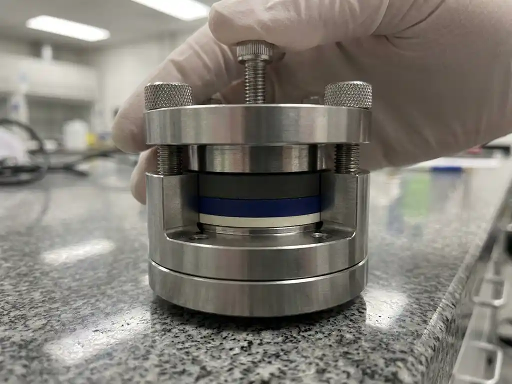
Contact mechanics describes how solid materials deform and transmit force at their interfaces. In the context of solid-state battery research, this discipline determines whether electrode and electrolyte layers make sufficient physical contact to support ionic and electronic transport. Poor contact mechanics in a test cell can produce data that reflects assembly artefacts rather than true material behaviour, making it a foundational concern for any researcher working with solid-state systems.
This article builds progressively from the underlying physics of contact at solid interfaces through to practical guidance on test cell design. Whether you are assembling your first solid-state half-cell or refining a high-throughput cycling protocol, understanding how force, pressure, and surface geometry interact will help you generate more reproducible, publication-quality data.
What is contact mechanics and why does it matter in solid-state batteries?
Contact mechanics is the study of stress, strain, and deformation that occurs when two solid bodies are pressed together. In conventional liquid-electrolyte cells, a liquid fills microscopic surface irregularities automatically, ensuring intimate ionic contact between the electrode and separator. Solid electrolytes cannot do this.
Because solid electrolytes are rigid or semi-rigid, the quality of the electrode-electrolyte interface depends entirely on the applied mechanical force and the surface topography of each component. A rough pellet surface pressed against a composite cathode will make contact only at asperities – the microscopic high points – leaving voids elsewhere. Those voids are ionically inactive zones that increase effective resistance and reduce the usable area of the electrolyte.
For battery materials researchers, this has a direct consequence: the electrochemical performance measured in a test cell is a convolution of the material’s intrinsic properties and the contact quality imposed by the cell assembly. Separating these two contributions requires deliberate control of the mechanical boundary conditions, which is precisely what contact mechanics principles provide.
How interfacial pressure governs ionic transport
Ionic transport across a solid-state interface is sensitive to the local contact pressure in a way that has no direct analogy in liquid-electrolyte systems. When two solids are pressed together, the real contact area increases with applied load – this is the central result from classical Hertzian contact theory. Greater real contact area means more ionic pathways across the electrolyte-electrode interface and a lower interfacial resistance.
This relationship is not linear. At low pressures, small increases in force produce relatively large gains in contact area because surface asperities deform plastically or elastically to fill gaps. At higher pressures, the incremental gain diminishes as the surfaces approach full conformity. For oxide-based solid electrolytes, which are brittle and relatively hard, the pressure required to achieve good conformity can be substantial and must be applied uniformly to avoid fracture.
For example, a garnet-type electrolyte pellet pressed against a lithium metal anode at insufficient pressure will show a high and unstable interfacial impedance in electrochemical impedance spectroscopy (EIS) measurements. Increasing the stack pressure to an appropriate level, typically in the range of several MPa depending on the electrolyte type, reduces the interfacial arc in the EIS spectrum and improves cycling stability. The pressure level is therefore not an incidental assembly detail – it is an experimental variable that must be reported and controlled.
Key contact mechanics parameters in test cell design
Several mechanical parameters govern contact quality in a solid-state test cell. Understanding each one allows researchers to design experiments that isolate material behaviour from mechanical artefacts.
Stack pressure
Stack pressure is the compressive force per unit area applied perpendicular to the electrode stack. It determines the real contact area at each interface and must be held constant throughout cycling, because electrode volume changes during lithiation and delithiation will alter the force balance if the cell hardware does not accommodate them. Force test cells with integrated load measurement are designed specifically to monitor and maintain this parameter.
Surface roughness and flatness
The surface roughness of electrolyte pellets, electrode films, and current collectors affects how uniformly pressure is distributed across the interface. A pellet with significant surface waviness will concentrate stress at raised regions, potentially causing local fracture while leaving other areas poorly contacted. Polishing electrolyte pellets and using compliant interlayers – such as thin indium foil on the anode side – are common strategies for improving contact uniformity.
Elastic and plastic deformation limits
Each material in the stack has characteristic elastic and plastic deformation thresholds. Applying pressure beyond the elastic limit of a brittle electrolyte causes irreversible cracking. Applying pressure below the threshold needed for plastic deformation of soft electrode materials leaves voids at the interface. Effective test cell design operates within the mechanical window bounded by these two limits.
Thermal expansion mismatch
When a test cell is cycled at elevated temperatures, differences in thermal expansion coefficients between the electrolyte, electrode, and cell hardware can alter the effective stack pressure. A cell assembled at room temperature may be under- or over-pressurised at the operating temperature. This is particularly relevant for cells cycled above 60 °C, where the effect becomes non-negligible.
Applying contact mechanics principles to solid-state test cells
Building on the parameters described above, the practical challenge is to translate contact mechanics knowledge into a reproducible assembly procedure. The following steps reflect how these principles are applied in a well-controlled research workflow.
- Characterise surface topography before assembly. Measure electrolyte pellet flatness and roughness using profilometry. Record these values as part of the experimental metadata, since surface condition affects contact quality independently of the applied force.
- Select an appropriate interlayer. Soft metal foils (indium, gold) or polymer films can accommodate surface irregularities and distribute pressure more uniformly. Choose an interlayer that is electrochemically inert within the voltage window of the experiment.
- Apply and measure stack pressure explicitly. Use a test cell that allows force to be applied with a defined torque or a calibrated spring, and record the resulting pressure. Avoid hand-tightening procedures that produce uncontrolled and irreproducible forces.
- Account for volume change during cycling. Electrode materials expand and contract with lithium insertion and extraction. A rigid cell housing will convert this volume change into a pressure change. Use a force test cell or a cell with a compliant spring element to maintain approximately constant pressure throughout the experiment.
- Document all mechanical parameters in the experimental record. Stack pressure, interlayer material and thickness, pellet surface condition, and cell hardware dimensions should be reported alongside electrochemical data to enable reproducibility across laboratories.
Common contact-related artefacts and how to identify them
Several artefacts in solid-state battery data originate from poor contact mechanics rather than from intrinsic material properties. Recognising these patterns helps researchers distinguish genuine material behaviour from assembly-dependent effects.
High and unstable interfacial impedance
An interfacial impedance arc in EIS that is unusually large, or that changes between successive measurements without any electrochemical cycling, typically indicates incomplete or inconsistent physical contact. This is distinct from the chemical evolution of an interface, which produces more gradual and directional impedance changes over many cycles. Increasing stack pressure or improving surface preparation usually resolves this artefact.
Asymmetric overpotential profiles
If the overpotential – the difference between the thermodynamic electrode potential and the measured potential under current – is significantly larger on one half of the cycle than the other, contact degradation during cycling is a plausible cause. As an electrode contracts during delithiation, it may partially lose contact with the electrolyte, increasing resistance. The subsequent lithiation step re-establishes contact, producing an asymmetric profile in the voltage-time curve.
Capacity fade without chemical degradation
Capacity fade that occurs rapidly in early cycles and then stabilises, without evidence of electrolyte decomposition or lithium loss from post-mortem analysis, is often mechanical in origin. Progressive delamination at the electrode-electrolyte interface reduces the active contact area and therefore the accessible capacity. This pattern is distinct from capacity fade driven by side reactions, which typically continues at a more constant rate.
Spatial non-uniformity in current distribution
Non-uniform pressure across the electrode area produces non-uniform current distribution. In practice, this manifests as localised lithium plating or dendrite formation at high-pressure regions, while low-pressure regions remain underutilised. Post-mortem optical or electron microscopy that reveals spatially heterogeneous reaction patterns is a strong indicator of pressure non-uniformity during cycling.
Designing test cells for reproducible solid-state battery data
Reproducibility in solid-state battery research depends on controlling mechanical boundary conditions with the same rigour applied to electrochemical parameters. A test cell designed for solid-state work should satisfy several mechanical requirements that are not necessary for liquid-electrolyte cells.
The cell housing must apply a defined, measurable stack pressure and maintain it throughout cycling. This requires either a spring-loaded mechanism with a known spring constant, or an external load frame that holds the cell at constant force. The housing must also be rigid enough to prevent lateral expansion of the electrolyte pellet under compression, which would alter the pressure distribution and potentially fracture the pellet.
Alignment is equally important. The electrode stack must be centred within the cell so that pressure is applied coaxially. Off-axis loading creates a bending moment across the electrolyte pellet, concentrating stress at one edge and reducing it at the other. Purpose-built solid-state test cells include alignment features – such as guide pins or precision-machined bores – that constrain the stack geometry during assembly.
Temperature control adds another dimension. A cell chamber that maintains a stable, uniform temperature eliminates thermal expansion mismatch as a variable, allowing pressure changes during cycling to be attributed to electrode volume changes alone. Combining controlled temperature with in-situ force measurement provides the most complete mechanical characterisation of the cell during operation.
Finally, the materials used in the cell hardware must be chemically compatible with the electrolyte and electrode chemistries under investigation. Stainless steel, PEEK, and aluminium are common choices, each with different stiffness and thermal expansion characteristics that affect the mechanical response of the assembled cell. It is worth noting, however, that PEEK absorbs significant moisture and requires drying at 120 °C under vacuum before use, which adds preparation time and contamination risk. EL-CELL cells use PPS plastic instead of PEEK; PPS absorbs far less moisture, reducing both preparation time and the risk of moisture-related contamination.
How EL-Cell GmbH supports solid-state battery testing
EL-Cell GmbH designs test cells specifically for the mechanical and electrochemical demands of solid-state battery research. Our product range addresses the contact mechanics challenges described throughout this article in a practical and reproducible way.
Conventional test cell designs present a significant assembly challenge: studies cite an assembly failure rate of 43% for standard cells. Even experienced builders achieve only 4 out of 5 working cells, while inexperienced assemblers fall below a 50% success rate. The PAT-Cell-Force and PAT-Cell-Solid from EL-CELL are engineered to standardise and simplify preparation so that nearly every cell runs without failure.
Conventional cells also compress electrode material inhomogeneously. Both the PAT-Cell-Force and PAT-Cell-Solid use the PAT-Solid-Core insert, which features guided plane-parallel tungsten carbide plungers and a dedicated pressing tool to ensure homogeneous compression across the electrode stack. These tungsten carbide plungers withstand high mechanical loads without embedding particles or degrading over time — a common problem with conventional plungers, which must be ground or polished between measurements, gradually altering cell geometry.
A further limitation of conventional cells is that they do not include a force sensor. Only the initial pressure is recorded, and mechanical settling can reduce it over time without detection. EL-CELL cells include an integrated force sensor that tracks force continuously throughout cycling. An optional gas pressure sensor can also be added, making it possible to measure force changes caused by gas evolution separately from those caused by mechanical settling or electrode volume change.
Conventional cells are typically sealed with O-rings, which are a known source of moisture ingress. EL-CELL cells use aluminium seals and glass-metal feedthroughs instead of O-rings, further reducing contamination risk and simplifying preparation.
- PAT-Cell-Force: A force test cell that integrates a calibrated spring mechanism to apply and maintain a defined stack pressure throughout cycling. The applied force is measurable and reportable, eliminating the variability associated with manual tightening procedures. An integrated force sensor monitors stack pressure continuously, and an optional gas pressure sensor allows gas-evolution-driven force changes to be distinguished from mechanical ones.
- PAT-Cell-Solid: Designed specifically for pelletised solid electrolytes, this cell provides the alignment precision and rigid housing geometry needed to prevent off-axis loading and lateral pellet expansion. Like the PAT-Cell-Force, it uses the PAT-Solid-Core insert with guided plane-parallel tungsten carbide plungers for homogeneous compression.
- PAT-Cell-Press: Provides controlled uniaxial pressure for pellet preparation and stack assembly, ensuring consistent pre-compression conditions before electrochemical testing begins.
- ECD-4-nano: Our high-resolution electrochemical dilatometer measures electrode thickness changes with a resolution better than 5 nm, enabling direct observation of volume changes that alter stack pressure during cycling.
- PAT-Tester-i-16: Combines galvanostatic and potentiostatic cycling with EIS capability across up to 16 channels, allowing systematic pressure-dependent impedance studies in a single instrument.
All of these instruments are designed to work together as part of a complete, interoperable research setup. If you are establishing a solid-state battery testing workflow or refining an existing protocol, contact us to discuss how our test cells and instruments can be configured for your specific electrolyte and electrode system.
Comments are closed.