


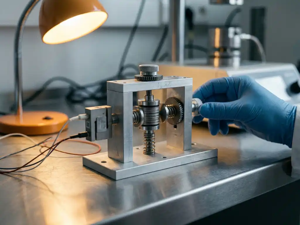
A force test cell is a battery test cell equipped with a load sensor that measures the mechanical force exerted by electrodes during electrochemical cycling. It records compressive stress in real time alongside voltage and current data. The sections below address the most common questions researchers ask when considering force measurement as part of their experimental workflow.
What mechanical forces occur inside a battery cell during cycling?
During charge and discharge, electrode materials expand and contract as ions intercalate into and de-intercalate from the host lattice. These volume changes generate compressive or tensile stress within the electrode stack, and that stress is transmitted to the cell casing as a measurable force. The magnitude and direction of the force depend on the active material, the state of charge, and the cycling rate.
In graphite anodes, lithiation proceeds through several staging transitions, each producing a distinct step-wise volume increase. At full lithiation to LiC6, graphite expands by roughly 10% in the c-axis direction. Silicon-based anodes are more extreme, with volumetric expansion exceeding 300% at full lithiation. On the cathode side, layered oxides such as NMC (lithium nickel manganese cobalt oxide) and LFP (lithium iron phosphate) also change volume, though typically by smaller amounts.
In a constrained cell geometry, these dimensional changes translate directly into force. When the electrodes are held between rigid platens, as in a force test cell, the stack cannot expand freely and instead builds pressure. This pressure varies cyclically with state of charge and accumulates over time as the cell ages.
How does a force test cell measure electrode stress?
A force test cell integrates a calibrated load cell into the cell body, positioned so that the electrode stack compresses or decompresses against it during cycling. The load cell converts mechanical force into an electrical signal, which is recorded continuously alongside the electrochemical data from the potentiostat or battery tester. The result is a time-resolved force profile correlated directly with voltage, current, and capacity.
The key design requirement is a rigid cell housing that constrains the stack without introducing compliance artefacts. If the housing deflects under load, the measured force will underestimate the true stress. High-quality force test cells use stiff metallic housings and precision-machined components to minimise this error.
Calibration is straightforward: the load cell is zeroed before cell assembly, and the applied pre-load (if any) is recorded as a baseline. During cycling, the signal represents the change in force relative to that baseline. Pre-loading the stack to a defined pressure is common practice, particularly for solid-state cells where intimate electrode-electrolyte contact depends on applied pressure.
Conventional test cells do not include a force sensor — only the initial pressure is set at assembly, and mechanical settling can reduce it over time without detection. The PAT-Cell-Force and PAT-Cell-Solid from EL-CELL both include an integrated force sensor that tracks these changes continuously. An optional gas pressure sensor can also be added, allowing force changes caused by gas evolution to be measured and distinguished from purely mechanical ones.
What can force data reveal that voltage curves cannot?
Force data captures mechanical events in the electrode that produce no clear electrochemical signature in the voltage profile. Phase transitions, particle cracking, gas evolution, and electrolyte decomposition can all produce changes in the force signal before they are visible in the capacity or voltage data. This makes force measurement a sensitive early indicator of degradation mechanisms.
- Phase transitions: In graphite, the staging transitions during lithiation appear as distinct inflections in the force curve, providing a mechanical fingerprint of the intercalation sequence that complements differential capacity analysis.
- Particle cracking: Repeated large-volume changes in materials such as silicon cause particle fracture over many cycles. As particles crack, the electrode loses mechanical cohesion and the force response gradually changes, often showing reduced peak force and altered hysteresis.
- Gas evolution: Gas generated within the cell, for example from electrolyte oxidation or lithium plating, increases the internal pressure and appears as an anomalous force increase that is not correlated with the normal charge-discharge cycle.
- SEI (Solid Electrolyte Interphase) growth: The SEI layer that forms on the anode surface during early cycles contributes to irreversible thickness increase. This shows up as a gradual baseline drift in the force signal across the first few formation cycles.
- Cycle-to-cycle drift: Progressive changes in the force baseline over hundreds of cycles reflect cumulative mechanical degradation, including electrode swelling, binder fatigue, and loss of stack pressure.
Voltage curves alone cannot distinguish between these mechanisms. Force data, when analysed alongside coulombic efficiency and capacity fade, allows researchers to attribute degradation to specific physical processes.
Which battery chemistries and electrode materials benefit most from force testing?
Force testing is most informative for electrode materials that undergo large or structurally complex volume changes during cycling. Silicon-dominant anodes, lithium metal, and solid-state cell configurations are the primary use cases, but the technique adds value across a broad range of chemistries.
Silicon and silicon-composite anodes are the clearest case. The extreme volume change of silicon makes mechanical stress a first-order concern for cell design and lifetime. Force data directly quantifies how different binder systems, particle sizes, and electrode architectures manage that stress.
Lithium metal anodes present a different challenge. Lithium plates and strips unevenly, and the force signal reflects the stochastic nature of that process. Monitoring force during lithium deposition can help identify conditions that promote dendritic growth or mossy lithium formation.
Solid-state batteries are particularly well suited to force test cells. Solid electrolytes are mechanically rigid and sensitive to contact pressure. Maintaining adequate stack pressure is essential for low interfacial resistance, and force measurement provides direct feedback on whether that pressure is maintained throughout cycling. This is one reason force test cells have become standard equipment in solid-state battery testing programmes.
NMC and NCA cathodes exhibit anisotropic lattice changes that generate stress at the particle level. At high states of charge, lattice contraction in the c-axis can cause intergranular cracking in polycrystalline particles. Force measurement at the cell level does not resolve individual particles, but it can detect the cumulative mechanical response associated with this degradation mode.
LFP cathodes undergo a two-phase reaction with relatively modest volume change, but force data is still useful for detecting anomalies in the phase transition and for characterising the mechanical behaviour of thick electrodes at high C-rates.
How is a force test cell integrated into a typical lab workflow?
A force test cell connects to a standard battery tester or potentiostat/galvanostat in the same way as any other test cell, with the addition of a data acquisition channel for the load cell signal. Most researchers record force data using a separate data logger synchronised to the electrochemical instrument, or use an instrument that natively supports auxiliary analogue inputs.
The typical workflow proceeds as follows:
- Cell assembly: Electrodes and separator are assembled under controlled atmosphere if required. The load cell is zeroed and the stack is placed in the cell housing. A defined pre-load may be applied using a torque-controlled fastener or a calibrated spring.
- Baseline recording: Before cycling begins, the resting force is recorded as a function of time to confirm that the assembly is stable and that there is no ongoing swelling from electrolyte uptake.
- Cycling with synchronised force acquisition: The battery tester runs the desired protocol (formation cycles, rate capability test, long-term cycling) while the force signal is recorded at the same time resolution as the electrochemical data.
- Data analysis: Force is plotted against time, voltage, and state of charge. Differential force analysis (dF/dQ or dF/dV) can be used to identify phase transitions and compare samples.
- Post-mortem correlation: If the cell is disassembled after testing, the force history can be correlated with physical observations such as electrode delamination, lithium plating marks, or electrolyte discolouration.
Force test cells are compatible with standard electrochemical techniques including cyclic voltammetry, galvanostatic intermittent titration technique (GITT), and electrochemical impedance spectroscopy (EIS), so they can be incorporated into any existing measurement sequence without modification.
What is the difference between a force test cell and an electrochemical dilatometer?
A force test cell measures the stress generated by a constrained electrode stack, while an electrochemical dilatometer measures the free linear expansion of an electrode under minimal or controlled load. The two techniques are complementary and answer different questions about electrode mechanics.
In a force test cell, the electrode stack is held between rigid platens. The electrodes cannot expand freely, so dimensional change is converted into force. The output is a force-versus-time or force-versus-state-of-charge curve. This configuration is relevant to how electrodes behave inside a real cell, where they are constrained by the casing.
In an electrochemical dilatometer, the electrode is free to expand in one direction, and a high-resolution displacement sensor records the thickness change. The output is a thickness-versus-time or thickness-versus-state-of-charge curve, expressed in absolute units (typically micrometres or nanometres). This configuration is used to characterise the intrinsic volume change of an electrode material under near-zero load, independent of cell design constraints.
The practical distinction matters for experimental design:
- Use a force test cell when you want to understand the mechanical loads that electrodes impose on the cell structure, or when you are evaluating how a cell responds to a defined stack pressure.
- Use an electrochemical dilatometer when you want to quantify the absolute dimensional change of an electrode material, compare materials, or characterise expansion kinetics at high resolution.
- Use both in parallel when you need a complete picture of both the dimensional change and the resulting mechanical stress, for example when optimising electrode formulations for a solid-state cell.
The resolution requirements also differ. Dilatometers such as the ECD-4-nano are designed to resolve sub-nanometre thickness changes, which requires a very low applied load and a highly sensitive displacement sensor. Force test cells do not need sub-nanometre resolution, but they do require accurate load cell calibration and a rigid housing to avoid compliance errors.
How EL-Cell GmbH supports force measurement in battery research
We design and manufacture test cells specifically for researchers who need to combine electrochemical and mechanical measurements in a single experiment. Our PAT-Cell-Force is built for exactly this purpose, providing calibrated force measurement alongside full electrochemical functionality in a format compatible with the rest of the PAT Series ecosystem.
For solid-state battery research, the PAT-Cell-Solid is designed to apply and maintain defined stack pressures, which is a prerequisite for reproducible solid electrolyte testing. Both cells connect directly to our PAT-Tester-i-16 instrument, which supports auxiliary analogue inputs for synchronised force data acquisition.
Both the PAT-Cell-Force and the PAT-Cell-Solid are designed to address well-documented limitations of conventional test cells. Assembly failure rates in conventional cells are high — studies cite a 43% failure rate overall, and even experienced researchers typically achieve only 4 out of 5 working cells, while inexperienced builders fall below 50%. The PAT-Cell-Force and PAT-Cell-Solid standardise and simplify preparation so that nearly every cell runs without failure.
Both cells use the PAT-Solid-Core insert, which features guided plane-parallel tungsten carbide plungers and a dedicated pressing tool to ensure homogeneous compression of electrode material — something conventional cells, which compress electrode material inhomogeneously, cannot guarantee. These tungsten carbide plungers also withstand high mechanical loads without embedding particles or degrading over time. Conventional plungers embed particles during use and must be ground or polished between measurements, gradually altering cell geometry; the tungsten carbide plungers used here eliminate that problem entirely.
Sealing is another area where conventional cells fall short. Standard designs rely on O-rings and PEEK housings, and PEEK absorbs significant moisture, requiring drying at 120°C under vacuum. EL-CELL cells use aluminum seals and glass-metal feedthroughs instead of O-rings, and PPS plastic instead of PEEK. PPS absorbs far less moisture, which reduces contamination risk and cuts preparation time.
What we offer for force-based battery research:
- Calibrated force test cells with rigid housings to minimise compliance artefacts
- Integrated force sensors with an optional gas pressure sensor for separating mechanical and gas-evolution contributions
- Test cells designed for solid-state and high-pressure applications
- Homogeneous electrode compression via guided tungsten carbide plungers and the PAT-Solid-Core insert
- Aluminum seals and glass-metal feedthroughs with PPS housings for reduced moisture uptake and faster preparation
- Fully integrated instrumentation that records electrochemical and mechanical data simultaneously
- High-resolution dilatometry with the ECD-4-nano for complementary thickness measurements
- A complete, interoperable research ecosystem under the PAT Series brand, from cell hardware to software
If you are setting up a force measurement workflow or need guidance on which cell configuration suits your electrode chemistry, contact us directly to discuss your experimental requirements.
Comments are closed.