


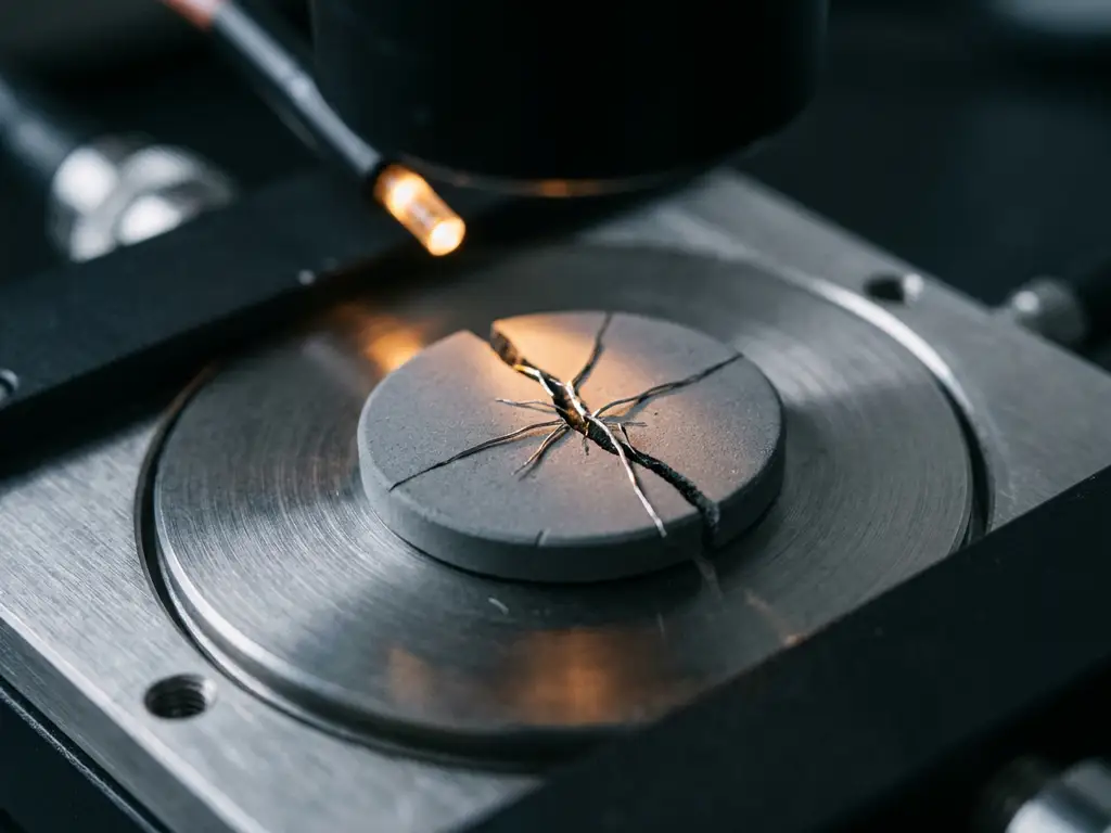
Dendrite formation in solid-state batteries is detected through a combination of electrochemical impedance spectroscopy (EIS), voltage monitoring during galvanostatic cycling, and post-mortem physical analysis. In solid-state systems, dendrites grow through grain boundaries and defects in the solid electrolyte rather than through a liquid medium, which makes their detection more demanding than in conventional liquid-electrolyte cells. The sections below address the mechanisms, methods, and experimental design choices that matter most for researchers studying this failure mode.
Why do dendrites form in solid-state batteries?
Lithium dendrites form in solid-state batteries when the localised current density at the lithium metal anode exceeds the rate at which lithium can be deposited uniformly. Rather than plating evenly, lithium preferentially deposits at surface irregularities, grain boundaries, and defect sites within the solid-state electrolyte, eventually propagating as a filament through the electrolyte bulk.
Several physical and electrochemical factors accelerate this process:
- Insufficient stack pressure: Poor contact between the lithium anode and the solid electrolyte creates voids that concentrate current density at contact points.
- Grain boundary conduction: In polycrystalline ceramics such as LLZO (lithium lanthanum zirconium oxide), lithium preferentially migrates along grain boundaries, which offer lower-resistance pathways for filament propagation.
- High current density: Operating above the critical current density (CCD) of the electrolyte triggers dendrite nucleation even in defect-free materials.
- Electronic conductivity in the electrolyte: A small but non-negligible electronic conductivity within the solid electrolyte can drive electrochemical reduction of lithium ions inside the material rather than at the interface.
Understanding which mechanism dominates in a given electrolyte system is essential for designing experiments that can reliably reproduce and detect dendrite growth.
What methods are used to detect dendrites in solid-state batteries?
Dendrite detection in solid-state battery testing relies on electrochemical signatures, physical inspection, and, where possible, in-situ imaging. No single method is sufficient on its own; researchers typically combine two or more approaches to confirm dendrite formation and distinguish it from other failure modes.
Electrochemical methods
- Galvanostatic cycling with voltage monitoring: A sudden voltage drop to zero or near-zero during a stripping or plating step is a primary indicator of an internal short circuit caused by a dendrite bridging the electrolyte.
- Critical current density testing: Stepwise increases in current density until the cell fails provide a quantitative threshold for dendrite nucleation in a given electrolyte.
- EIS: Changes in impedance spectra across cycles reveal the growth of resistive or conductive pathways through the electrolyte (discussed in detail in the next section).
Physical and imaging methods
- Post-mortem cross-sectional analysis: Scanning electron microscopy (SEM) and focused ion beam (FIB) sectioning can reveal dendrite filaments within the electrolyte after cell disassembly.
- Synchrotron X-ray tomography: Provides three-dimensional imaging of dendrite morphology without destructive sectioning, though access is limited to specialised facilities.
- Optical in-situ observation: Cells with optically transparent windows allow direct visual monitoring of lithium deposition at the electrolyte interface during cycling. The ECC-Opto-10 is designed for exactly this type of in-situ optical monitoring during electrochemical testing.
How does EIS reveal dendrite growth during cycling?
Electrochemical impedance spectroscopy reveals dendrite growth by tracking changes in the interfacial and bulk resistance of the cell across repeated cycles. As a dendrite propagates through the solid electrolyte, the bulk resistance of the electrolyte decreases measurably, whilst the interfacial impedance at the anode side may simultaneously increase due to contact loss or SEI layer (Solid Electrolyte Interphase) disruption.
Key signatures to monitor in impedance spectra include:
- Reduction in bulk electrolyte resistance: A progressive decrease in the high-frequency real-axis intercept indicates a conductive pathway forming through the electrolyte.
- Emergence of a new low-frequency arc: This can indicate electronic leakage through the electrolyte, consistent with partial dendrite penetration.
- Suppression of the interfacial arc: Once a dendrite bridges the electrolyte, the interfacial impedance collapses as the short circuit dominates the electrical response.
EIS is most informative when collected periodically throughout cycling rather than only at the beginning and end of a test. Tracking impedance evolution as a function of cycle number allows researchers to identify the onset of dendrite growth before a hard short circuit occurs. The PAT-Tester-i-16 supports exactly this workflow, enabling full EIS capability alongside galvanostatic cycling across all 16 channels simultaneously.
What role does cell pressure play in dendrite suppression and detection?
Applied stack pressure directly influences both the likelihood of dendrite formation and the reliability of its detection. Adequate pressure ensures intimate contact between the lithium anode and the solid electrolyte, reducing void formation and distributing current density more uniformly across the interface. Insufficient pressure is one of the most common experimental artefacts that triggers premature dendrite growth in laboratory cells.
The relationship between pressure and dendrite behaviour is not straightforward, however:
- Too little pressure creates interfacial voids that concentrate local current density, promoting dendrite nucleation at operating currents well below the intrinsic CCD of the electrolyte.
- Optimal pressure maintains conformal contact throughout cycling, including during volume changes associated with lithium stripping and plating.
- Excessive pressure can fracture brittle ceramic electrolytes such as garnet-type LLZO, introducing mechanical cracks that then serve as preferential dendrite propagation pathways.
For reproducible dendrite studies, pressure must be controlled and monitored throughout the experiment. Conventional test cells do not include a force sensor — only the initial pressure is set, and mechanical settling can reduce it over time without detection. The PAT-Cell-Force addresses this directly by integrating a calibrated force sensor that records stack pressure continuously during electrochemical testing. An optional gas pressure sensor can also be added to measure force changes caused by gas evolution separately from mechanical ones, allowing researchers to distinguish between different sources of pressure variation during cycling.
Which test cell designs are best suited for dendrite studies?
Test cells for dendrite studies in solid-state batteries must satisfy several requirements simultaneously: controlled and measurable stack pressure, compatibility with rigid ceramic or polymer electrolyte pellets, the ability to run EIS alongside galvanostatic cycling, and ideally some form of in-situ monitoring capability. Standard coin cells are poorly suited to this work because they do not allow pressure control or continuous impedance measurement under defined conditions.
The most suitable cell formats share the following characteristics:
- Uniaxial pressure application: A spring-loaded or externally pressurised design that maintains consistent contact force throughout cycling.
- Flat, parallel electrode geometry: Ensures uniform current distribution across the electrolyte cross-section, which is essential for interpreting EIS data and for reproducible CCD measurements.
- Integrated force measurement: Allows researchers to correlate dendrite onset with specific pressure values rather than relying on nominal spring constants.
- Compatibility with solid electrolyte pellets: The cell must accommodate the thickness and rigidity of sintered ceramic discs without cracking them during assembly.
Conventional test cells also present a significant practical challenge: studies cite an assembly failure rate as high as 43%. Even experienced builders achieve only around 4 out of 5 working cells, while inexperienced ones fall below 50%. The PAT-Cell-Force and PAT-Cell-Solid from EL-CELL address this through standardised preparation procedures and the PAT-Solid-Core insert, which uses guided plane-parallel tungsten carbide plungers and a dedicated pressing tool to ensure homogeneous compression of electrode material — something conventional cells cannot reliably achieve. As a result, nearly every assembled cell runs without failure.
The choice of materials also matters for preparation reliability. Conventional cells are typically sealed with O-rings and often use PEEK housings, which absorb significant moisture and require drying at 120°C under vacuum. EL-CELL cells use aluminum seals and glass-metal feedthroughs instead of O-rings, and PPS plastic instead of PEEK. PPS absorbs substantially less moisture, reducing contamination risk and cutting preparation time. The tungsten carbide plungers used in EL-CELL cells further contribute to long-term reliability: unlike conventional plungers that embed particles during use and must be ground or polished between measurements — gradually altering cell geometry — tungsten carbide withstands high mechanical loads without this degradation.
Cells with optical access add further capability by enabling direct visual observation of lithium deposition at the electrolyte interface. For solid-state battery testing, the PAT-Cell-Solid and PAT-Cell-Force are both well suited to dendrite research, with the latter offering continuous force monitoring as a key experimental variable.
How do you distinguish a dendrite short circuit from other failure modes?
A dendrite-induced short circuit produces a characteristic electrochemical signature that can be distinguished from other failure modes by the combination of voltage behaviour, impedance response, and the conditions under which failure occurs. The key distinguishing feature is a sudden, irreversible voltage drop to near-zero during a plating or stripping step, occurring without any gradual degradation in capacity or coulombic efficiency in preceding cycles.
Comparing failure signatures helps clarify the diagnosis:
- Dendrite short circuit: Abrupt voltage collapse during plating, often at a specific current density threshold; EIS shows a drop in bulk electrolyte resistance prior to failure; failure is typically irreversible.
- Electronic leakage (partial short): Gradual reduction in open-circuit voltage over time; coulombic efficiency falls progressively; EIS shows a low-frequency arc developing before a hard short occurs.
- Interfacial delamination: Rising overpotential during cycling; increasing interfacial resistance in EIS; no sudden voltage collapse; often pressure-dependent and partially reversible.
- Electrolyte cracking: May present similarly to a dendrite short but is typically associated with a mechanical event (assembly, thermal cycling) rather than electrochemical cycling; post-mortem inspection reveals fracture planes rather than filaments.
Post-mortem analysis is often necessary to confirm the mechanism definitively. SEM cross-sections that reveal metallic lithium filaments within the electrolyte confirm dendrite penetration, whilst the absence of filaments in the presence of a short circuit points towards cracking or electronic conduction as the primary failure mode.
How EL-Cell GmbH supports dendrite research in solid-state batteries
EL-Cell GmbH provides the instrumentation and test cell hardware needed to study dendrite formation systematically under controlled, reproducible conditions. Our product ecosystem is designed so that electrochemical testing, pressure control, impedance spectroscopy, and in-situ monitoring can all be combined within a single, compatible setup.
Specifically, we offer:
- PAT-Cell-Force: A test cell with an integrated, calibrated force sensor for continuous stack pressure monitoring during cycling, essential for correlating dendrite onset with mechanical contact conditions. An optional gas pressure sensor allows force changes from gas evolution to be measured independently of mechanical pressure changes.
- PAT-Cell-Solid: Designed for solid-state electrolyte pellets, providing the flat, parallel geometry and pressure compatibility required for mechanistically clean dendrite experiments. Both the PAT-Cell-Force and PAT-Cell-Solid use the PAT-Solid-Core insert with guided plane-parallel tungsten carbide plungers and a dedicated pressing tool for homogeneous electrode compression and consistent cell geometry across measurements.
- PAT-Tester-i-16: A 16-channel battery tester with full potentiostat/galvanostat (PStat/GStat) and EIS capability, enabling impedance tracking across the full cycling history of each cell in parallel.
- EL-Software: Integrated software for designing test protocols that combine galvanostatic cycling with periodic EIS measurements, allowing researchers to monitor impedance evolution as a function of cycle number without manual intervention.
All components are designed to work together as part of the PAT Series ecosystem, reducing compatibility issues and simplifying experimental setup. If you are designing a dendrite study and would like to discuss which cell format and instrument configuration best fits your electrolyte system, contact our Application Laboratory directly for technical guidance.
Comments are closed.