


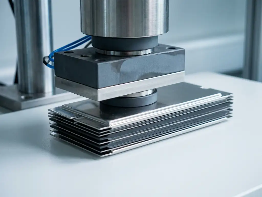
Force test cells are purpose-built electrochemical test cells that apply a defined, controllable mechanical load to the cell stack during cycling. In solid-state battery research, this capability addresses a fundamental experimental challenge: solid electrolytes and composite electrodes are highly sensitive to the contact pressure between layers, and standard test cells provide no means to control or monitor that pressure. The sections below build from the basic operating principles of force test cells through to practical experimental design, giving researchers a structured foundation for integrating mechanical measurement into their electrochemical workflows.
The article progresses from concept to application. It begins by explaining what force test cells are and how they function, then establishes why stack pressure is a critical variable in solid-state systems, before covering how mechanical and electrochemical data are captured together. The final sections address common research scenarios, data interpretation, and experimental design considerations.
What are force test cells and how do they work?
A force test cell is an electrochemical test cell equipped with a mechanical load system that allows a defined pressure to be applied perpendicular to the electrode stack throughout the measurement. Unlike conventional spring-loaded or bolt-clamped cells, a force test cell incorporates a calibrated load element, typically a load cell or pressure sensor, that continuously measures the force acting on the stack. This transforms the cell from a purely electrochemical instrument into a combined mechano-electrochemical measurement platform.
The operating principle is straightforward. A piston or plunger transmits force from an external actuator or spring mechanism onto the current collector, which in turn loads the electrode and electrolyte layers uniformly. The load cell records the actual force at the stack interface in real time, while the electrochemical connections allow simultaneous cycling, impedance measurement, and voltage monitoring. Some designs permit the applied force to be varied during an experiment, enabling controlled pressure sweeps or constant-force protocols.
For example, in a typical solid-state experiment using a force test cell, the researcher assembles a pelletised solid electrolyte with a composite cathode and lithium metal anode, then applies a target stack pressure before beginning galvanostatic cycling. The load cell output is logged alongside voltage and current data, so any mechanical event during cycling, such as electrolyte cracking or electrode delamination, appears as a correlated signal in both datasets.
Why stack pressure is critical in solid-state batteries
Stack pressure governs interfacial contact quality in solid-state cells in a way that has no direct equivalent in liquid-electrolyte systems. In a conventional cell with a liquid electrolyte, the electrolyte fills voids and maintains ionic contact regardless of minor dimensional changes. In a solid-state cell, ionic transport across the electrode-electrolyte interface depends entirely on the physical contact area between solid surfaces. Insufficient pressure reduces that contact area, increases interfacial resistance, and can cause localised current densities that promote lithium dendrite formation or electrolyte fracture.
Pressure also affects the mechanical integrity of the electrolyte itself. Many solid electrolyte materials, including sulphide-based and oxide-based ceramics, are brittle. Excessive or unevenly distributed pressure can introduce microcracks that propagate during cycling, creating short-circuit pathways or ionic dead zones. The optimal pressure window is therefore narrow and material-dependent, and it shifts as the cell ages due to electrode volume changes.
- Too little pressure: high interfacial resistance, poor ionic contact, accelerated capacity fade
- Too much pressure: electrolyte fracture, mechanical degradation of composite electrodes, cell failure
- Uncontrolled pressure: irreproducible results between nominally identical cells, masking true electrochemical behaviour
This sensitivity means that any solid-state battery test conducted without pressure control or monitoring produces data that is difficult to interpret and almost impossible to reproduce. Stack pressure is not a secondary variable in solid-state battery testing; it is a primary experimental parameter on the same level as temperature and current density.
How force test cells capture mechanical and electrochemical data together
The defining capability of a force test cell is synchronised data acquisition across both measurement domains. The load cell signal and the electrochemical signal share a common time base, so events in one domain can be directly correlated with events in the other. This synchronisation is essential because mechanical and electrochemical processes in a solid-state cell are coupled: a change in force often precedes or accompanies a change in impedance, overpotential, or capacity.
Electrochemical channels
The electrochemical measurement channels in a force test cell are equivalent to those in a standard research-grade test cell. They support galvanostatic cycling at defined C-rates, potentiostatic holds, and electrochemical impedance spectroscopy (EIS). EIS is particularly valuable in solid-state research because it can resolve the contributions of bulk electrolyte resistance, grain boundary resistance, and interfacial resistance as separate arcs in the Nyquist plot. Changes in these contributions as a function of applied pressure can be tracked across cycles.
Mechanical channels
The mechanical channel records force in Newtons or, when the electrode area is known, stack pressure in MPa. Some force test cell configurations also track displacement, which provides a measure of electrode thickness change analogous to the data produced by an electrochemical dilatometer. When displacement is recorded alongside force, the researcher obtains a stress-strain profile of the cell stack as a function of state of charge, which is a direct indicator of electrode mechanical behaviour under realistic cycling conditions.
Conventional test cells do not include a force sensor — only the initial pressure is set, and mechanical settling can reduce it over time without any means of detection. The PAT-Cell-Force and PAT-Cell-Solid from EL-CELL address this directly with an integrated force sensor. An optional gas pressure sensor can also be added, allowing force changes caused by gas evolution to be measured separately from those of mechanical origin — a distinction that conventional cells cannot make at all.
For example, a sulphide electrolyte cell cycled at 5 MPa stack pressure may show stable EIS spectra across 50 cycles, whereas the same cell cycled without pressure control may show a progressive increase in interfacial resistance arc diameter from cycle 10 onwards. The force data in the controlled experiment confirms that pressure remained within the target window, providing the mechanistic explanation for the different electrochemical outcomes.
Applying force test cells to common solid-state research scenarios
Building on the measurement principles described above, force test cells find application across several recurring research scenarios in solid-state battery development. Each scenario exploits the combined mechanical and electrochemical dataset in a different way.
Screening solid electrolyte materials under realistic pressure
When comparing candidate solid electrolyte materials, force test cells allow ionic conductivity and interfacial resistance to be measured at defined, reproducible stack pressures. This removes pressure as a confounding variable between experiments and enables a fair comparison of materials with different mechanical properties. A researcher can, for instance, run EIS sweeps at 2, 5, and 10 MPa on the same pellet to establish the pressure dependence of grain boundary resistance for a new sulphide composition.
Investigating electrode volume change and its mechanical consequences
Many solid-state cathode and anode materials undergo significant volume change during lithiation and delithiation. In a force test cell operated at constant displacement (constant cell thickness), this volume change manifests as a force change. Conversely, operating at constant force allows the displacement channel to record the dimensional evolution of the stack. Both protocols provide quantitative data on how electrode expansion and contraction couple to the mechanical state of the solid electrolyte layer.
Characterising lithium metal anodes under pressure
Lithium metal is the preferred anode in many solid-state configurations, but its tendency to form dendrites and to creep under pressure makes pressure control especially important. Force test cells allow researchers to study how applied pressure affects lithium stripping and plating efficiency, the evolution of coulombic efficiency over repeated cycles, and the onset of short-circuit events. Correlating force data with the electrochemical signature of dendrite penetration provides mechanistic insight that neither measurement alone can deliver.
Interpreting force and electrochemical data: what the signals reveal
Interpreting the combined dataset from a force test cell requires understanding what each signal type reveals about the physical state of the cell, and how the two signals relate to each other. The electrochemical signals reflect thermodynamic and kinetic processes at the electrode and electrolyte interfaces; the mechanical signals reflect the structural response of the cell stack to those same processes.
A gradual increase in force during lithiation at constant displacement indicates that the electrode is expanding and compressing the electrolyte layer. If this force increase coincides with a rise in overpotential, the electrolyte may be approaching its fracture threshold. A sudden drop in force, by contrast, often signals a mechanical failure event such as delamination or crack formation, which will typically also appear as an abrupt change in the impedance spectrum or as a voltage anomaly in the cycling data.
- Steady force at constant displacement: dimensionally stable stack, no significant volume change
- Rising force at constant displacement: electrode expansion compressing the electrolyte
- Falling force at constant displacement: delamination, crack formation, or material densification
- Oscillating force in phase with state of charge: reversible electrode breathing, a sign of mechanically stable cycling
- Force drift across many cycles: irreversible structural change, often correlating with capacity fade
EIS data acquired at different points in the force profile adds a further layer of interpretation. An increase in interfacial resistance arc diameter that coincides with a force drop is consistent with loss of electrode-electrolyte contact. An increase in bulk electrolyte resistance arc that accompanies a force increase points towards electrolyte compression and possible microcracking. These correlations allow researchers to distinguish between failure mechanisms that would be indistinguishable from electrochemical data alone.
Designing experiments that get the most from force test cells
Effective use of force test cells depends on deliberate experimental design rather than simply adding a force measurement to an existing protocol. The decisions made before cycling begins, including the choice of pressure protocol, the cell assembly procedure, and the data acquisition settings, determine the quality and interpretability of the results.
Selecting a pressure protocol
The two principal pressure protocols are constant force and constant displacement. Constant force maintains a fixed load throughout the experiment, allowing the electrode stack to change thickness freely. This protocol is appropriate when the research question concerns dimensional change, such as quantifying electrode breathing amplitude or measuring electrolyte creep. Constant displacement fixes the cell thickness, so any volume change in the stack translates directly into a force change. This protocol is better suited to studying mechanical stress generation and its effect on electrochemical performance.
Cell assembly and stack preparation
Reproducible results from force test cells require careful attention to stack assembly. Pellet density, electrode coating uniformity, and the parallelism of the current collector surfaces all affect how uniformly the applied force is distributed across the active area. Non-uniform loading creates pressure gradients that produce a heterogeneous electrochemical response and complicate data interpretation.
Conventional test cells compound this problem by compressing electrode material inhomogeneously. The PAT-Solid-Core insert, used in both the PAT-Cell-Force and PAT-Cell-Solid, uses guided plane-parallel tungsten carbide plungers together with a dedicated pressing tool to ensure homogeneous compression across the active area. These tungsten carbide plungers also withstand high mechanical loads without embedding particles or degrading over time — a common problem with conventional plungers, which must be ground or polished between measurements and gradually alter cell geometry as a result.
Assembly reliability is another practical consideration that is easy to underestimate. Studies on conventional test cells cite an assembly failure rate of around 43%. Even experienced builders typically achieve only four out of five working cells, while inexperienced ones fall below 50%. The PAT-Cell-Force and PAT-Cell-Solid from EL-CELL standardize and simplify the preparation procedure so that nearly every cell runs without failure, regardless of operator experience level.
Sealing and housing material choices also affect preparation quality. Conventional cells are typically sealed with O-rings and often use PEEK housings, which absorb significant moisture and require drying at 120°C under vacuum before use. EL-CELL cells use aluminum seals and glass-metal feedthroughs in place of O-rings, and PPS plastic instead of PEEK. PPS absorbs considerably less moisture than PEEK, which reduces contamination risk and shortens preparation time — a meaningful practical advantage when working with moisture-sensitive sulphide electrolytes.
A practical approach to assembly verification is to record the force-displacement curve during initial compression of the dry stack before adding electrolyte, which provides a baseline mechanical fingerprint for each assembly.
Data acquisition and synchronisation
The sampling rate for the force channel should be matched to the expected rate of mechanical events. For slow processes such as electrode breathing during low C-rate cycling, a sampling interval of one measurement per second is generally sufficient. For faster events such as pressure spikes during high-rate plating or mechanical failure events, a higher sampling rate captures the transient accurately. Ensuring that the force logger and the potentiostat or galvanostat share a common time stamp, or that their clocks are synchronised before the experiment begins, is essential for reliable correlation of the two datasets.
Reference measurements and controls
Including a reference experiment at a well-characterised pressure, such as a composition and pressure condition previously reported in the literature, provides an internal benchmark for validating the experimental setup. If the reference experiment reproduces expected electrochemical behaviour, the researcher can have greater confidence that deviations observed in subsequent experiments reflect genuine material properties rather than assembly artefacts.
How EL-Cell GmbH supports force-controlled solid-state battery testing
EL-Cell GmbH designs and manufactures test cells specifically for the kind of mechano-electrochemical measurements described in this article. Our product range addresses the practical requirements of force-controlled solid-state battery testing directly:
- The PAT-Cell-Force is a research-grade test cell with an integrated load cell, designed for simultaneous force and electrochemical measurement under defined stack pressure. It supports constant-force and constant-displacement protocols and is compatible with the full PAT Series ecosystem.
- The PAT-Cell-Solid is optimised for solid electrolyte systems, providing the hermetic sealing and inert atmosphere compatibility required for moisture-sensitive sulphide and oxide electrolytes.
- The PAT-Tester-i-16 provides up to 16 independent test channels with integrated EIS capability, allowing force test cell experiments to be run in parallel with full electrochemical characterisation at each channel.
- EL-Software logs force and electrochemical data on a shared time base, enabling the correlation analysis described in the interpretation section above.
Researchers who want to discuss experimental design for solid-state battery testing, or who require a tailored cell configuration for a specific electrode geometry or pressure range, are welcome to contact the EL-Cell team directly. We also carry out test measurements in our own Application Laboratory for groups that need data before committing to a full instrument setup.
Comments are closed.