


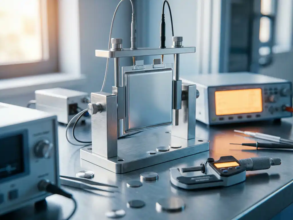
Solid-state battery testing protocols differ by application primarily because each use case imposes distinct mechanical, thermal, and electrochemical boundary conditions that a single generic protocol cannot satisfy. The electrolyte chemistry — oxide, sulfide, or polymer — further determines which measurement techniques are valid and what cell hardware is required. The sections below address the most common questions researchers raise when designing or adapting solid-state battery testing protocols.
What makes solid-state battery testing fundamentally different from liquid-cell testing?
Solid-state battery testing differs from liquid-electrolyte cell testing because the electrolyte is a rigid or semi-rigid solid that cannot conform to electrode surfaces under its own flow. This changes nearly every aspect of cell assembly, stack pressure management, and electrochemical measurement interpretation. Ionic transport at solid-solid interfaces is governed by contact quality rather than wetting, which means interfacial resistance is a direct function of the applied mechanical load.
In a conventional liquid-electrolyte cell, the separator and electrolyte fill the void space between electrodes, ensuring continuous ionic contact even as electrodes expand and contract during cycling. In a solid-state cell, any loss of physical contact at the electrode-electrolyte interface produces an immediate and measurable increase in interfacial resistance. Researchers must therefore control stack pressure actively throughout cycling, not just during initial assembly.
Additional differences that affect solid-state battery protocols include:
- The absence of a liquid phase eliminates risks of electrolyte leakage but introduces new failure modes such as electrolyte cracking and delamination
- Electrochemical impedance spectroscopy (EIS) spectra contain overlapping contributions from grain boundaries, electrode-electrolyte interfaces, and bulk electrolyte that require careful deconvolution
- Temperature sensitivity is more pronounced for polymer and composite electrolytes, requiring tighter thermal control during testing
- Cell assembly often requires dry-room or inert-atmosphere conditions, particularly for sulfide-based electrolytes
How do testing protocols differ for oxide, sulfide, and polymer solid electrolytes?
Testing protocols for solid electrolytes vary significantly by chemistry because oxide, sulfide, and polymer electrolytes differ in mechanical stiffness, atmospheric sensitivity, processing temperature, and the pressure conditions required to form low-resistance interfaces. Each class demands a tailored approach to cell assembly, stack pressure, and measurement conditions.
Oxide electrolytes
Oxide electrolytes such as garnet-type Li7La3Zr2O12 (LLZO) and NASICON-type materials are mechanically hard and chemically stable in air. Protocols for oxide electrolytes typically require sintered pellets, high-temperature co-sintering of electrode-electrolyte assemblies, and elevated stack pressures to achieve adequate interfacial contact. EIS measurements on oxide cells often show a well-separated bulk grain-boundary arc at frequencies above 100 kHz, which can be resolved with broadband impedance spectroscopy.
Sulfide electrolytes
Sulfide electrolytes such as argyrodite (Li6PS5Cl) and LGPS-type materials are mechanically soft and can be cold-pressed at room temperature, which simplifies cell fabrication. However, they are highly sensitive to atmospheric moisture and oxygen, requiring strict inert-atmosphere handling throughout assembly and testing. Stack pressures for sulfide cells are generally lower than for oxide cells, but pressure uniformity remains critical. Researchers should also account for the risk of H2S evolution when designing cell hardware and safety protocols.
Polymer electrolytes
Polymer electrolytes, including polyethylene oxide (PEO)-based systems, require elevated operating temperatures — typically 60 °C to 80 °C — to achieve sufficient ionic conductivity. Testing protocols must therefore include precise thermal management, and electrochemical measurements should only be performed once the cell has reached thermal equilibrium. At operating temperature, polymer electrolytes become viscoelastic, which reduces the mechanical stack pressure required but introduces creep behaviour that must be accounted for in long-term cycling experiments.
What testing protocols apply to automotive versus academic research applications?
Automotive solid-state battery testing protocols prioritise cycle life, rate capability, and performance under realistic operating conditions, including temperature extremes and high current densities. Academic research protocols are typically designed to isolate specific electrochemical phenomena, often using simplified half-cell geometries and lower current densities to maximise mechanistic resolution.
In automotive-oriented testing, key protocol requirements include:
- Full-cell configurations with commercially relevant electrode loadings (typically above 3 mAh/cm²)
- Cycle life assessment at C-rates representative of fast-charging scenarios (1C and above)
- Temperature cycling protocols that cover the operational range from approximately -20 °C to +60 °C
- Calendar ageing tests under controlled state-of-charge conditions
- Post-mortem analysis to identify failure mechanisms such as lithium dendrite penetration or electrolyte cracking
Academic research protocols, by contrast, are more likely to involve:
- Half-cell measurements against lithium metal reference electrodes to decouple anode and cathode contributions
- Low C-rates (C/10 or lower) to minimise kinetic overpotentials and isolate thermodynamic behaviour
- Incremental capacity analysis and differential voltage analysis to track phase transitions
- In-situ and operando measurements to monitor structural and dimensional changes in real time
The choice of test cell hardware must reflect these differences. A cell designed for operando X-ray diffraction in an academic setting has very different mechanical and geometric requirements from one intended for long-term automotive cycle-life testing. The PAT Series offers a modular platform that can be configured to meet both types of requirements within a common hardware ecosystem.
Why is stack pressure control critical in solid-state battery testing?
Stack pressure control is critical in solid-state battery testing because the quality of ionic contact at solid-solid interfaces is directly proportional to the compressive force applied across the cell stack. Insufficient pressure produces high interfacial resistance and poor electrochemical performance, while excessive pressure can fracture brittle electrolyte pellets or cause plastic deformation in soft electrode materials.
During cycling, electrode materials expand and contract as lithium ions are inserted and extracted. In a liquid-electrolyte cell, the electrolyte accommodates this volume change passively. In a solid-state cell, volume changes translate directly into mechanical stress at the electrolyte interface. Without active pressure control, interfacial resistance will drift over the course of a measurement, making it impossible to compare impedance spectra recorded at different states of charge on a consistent basis.
Conventional test cells do not include a force sensor — only the initial pressure is set, and mechanical settling during cycling can reduce it over time without any indication to the researcher. The PAT-Cell-Force addresses this directly by integrating a calibrated force sensor into the cell body, so that stack pressure is recorded continuously alongside electrochemical data throughout the experiment. An optional gas pressure sensor can also be added, allowing force changes caused by gas evolution to be measured and distinguished from purely mechanical ones.
Practically, researchers should:
- Define a target stack pressure before beginning any electrochemical protocol and verify it is maintained throughout cycling
- Use load cells or pressure-sensing hardware integrated into the test cell to monitor pressure continuously
- Report the applied stack pressure alongside all electrochemical data, as it is a key experimental variable that affects reproducibility
- Select pressure values appropriate to the electrolyte class — hard oxide pellets typically require higher pressures than soft sulfide compacts
How should EIS measurements be adapted for solid-state battery characterisation?
EIS measurements for solid-state battery characterisation require a broader frequency range, more careful equivalent circuit selection, and tighter control of temperature and stack pressure compared to liquid-electrolyte cell measurements. The impedance spectrum of a solid-state cell typically contains multiple overlapping semicircles corresponding to bulk electrolyte resistance, grain boundary resistance, and electrode-electrolyte interfacial resistance — contributions that are absent or merged in liquid-cell spectra.
Key adaptations for solid-state EIS protocols include:
- Frequency range: Extend the upper frequency limit to at least 1 MHz to resolve bulk and grain boundary contributions in oxide electrolytes. Polymer electrolytes may not require such high frequencies but benefit from measurements at multiple temperatures.
- Perturbation amplitude: Use small-signal amplitudes (typically 5–10 mV) to remain within the linear response regime, particularly important for thin or high-resistance solid electrolytes.
- Temperature control: Record all EIS spectra at a defined, stable temperature. Even small temperature fluctuations shift the ionic conductivity of solid electrolytes significantly, making spectra recorded at different temperatures incomparable.
- State of charge: Document the state of charge at which each EIS measurement is taken. Interfacial resistance in solid-state cells is state-of-charge dependent, and comparing spectra without this information leads to ambiguous conclusions.
- Equivalent circuit modelling: Avoid applying equivalent circuits developed for liquid-electrolyte cells directly to solid-state data. The Solid Electrolyte Interphase (SEI) layer that forms on the anode surface during early cycles contributes an additional impedance element that must be accounted for separately.
The PAT-Tester-i-16 supports EIS measurements across a frequency range suitable for solid-state characterisation and can be combined with temperature-controlled cell chambers to ensure isothermal measurement conditions.
What role do in-situ and operando techniques play in solid-state battery testing?
In-situ and operando techniques are particularly valuable in solid-state battery testing because many of the critical failure mechanisms — electrolyte cracking, interfacial delamination, and lithium dendrite growth — occur during electrochemical operation and cannot be observed after the fact in post-mortem analysis alone. Operando measurements allow researchers to correlate electrochemical signatures with structural and dimensional changes as they occur.
The most widely applied operando techniques for solid-state battery testing include:
- Operando dilatometry: Measures the thickness change of the cell stack as a function of state of charge, providing direct information about electrode volume change and electrolyte deformation. High-resolution dilatometry with sub-nanometre sensitivity can resolve individual phase transitions in electrode materials.
- Operando X-ray diffraction: Tracks crystallographic phase changes in electrode and electrolyte materials during cycling. Requires test cells with X-ray transparent windows and precise geometric tolerances.
- Operando EIS: Records impedance spectra at regular intervals during cycling to track the evolution of interfacial resistance, SEI formation, and electrolyte degradation over time.
- Operando optical microscopy: Enables direct visualisation of lithium deposition morphology and crack propagation in transparent or semi-transparent cell configurations such as the ECC-Opto-10.
For dilatometric measurements, resolution requirements in solid-state systems are demanding because the dimensional changes associated with electrolyte deformation and interfacial contact loss can be small. The ECD-4-nano electrochemical dilatometer, with a thickness resolution of better than 5 nm, is well suited to resolving these small but mechanistically significant changes.
Operando techniques also support the validation of computational models. By providing time-resolved experimental data on mechanical and electrochemical evolution, they allow researchers to test and refine predictions about solid-state battery degradation mechanisms under realistic cycling conditions.
How EL-Cell GmbH supports solid-state battery testing
EL-Cell GmbH designs and manufactures test cell hardware, potentiostats, galvanostats, and dilatometers that address the specific requirements of solid-state battery testing protocols described above. Our product ecosystem is built around reproducibility, mechanical precision, and compatibility across instruments — qualities that are particularly important when working with solid electrolytes where interfacial contact and stack pressure directly determine data quality. The PAT Core Concept underpins this ecosystem, enabling a common cell format to be used across a wide range of measurement techniques and instrument combinations.
Reproducibility begins at the assembly stage. Conventional test cells have a high assembly failure rate — studies cite figures as high as 43%, and even experienced builders report only around 4 out of 5 cells working correctly, while inexperienced ones fall below 50%. The PAT-Cell-Force and PAT-Cell-Solid from EL-CELL standardize and simplify preparation so that nearly every cell runs without failure. Both cells use the PAT-Solid-Core insert, which features guided plane-parallel tungsten carbide plungers and a dedicated pressing tool to ensure homogeneous compression of electrode material — something conventional cells, which compress electrode material inhomogeneously, cannot reliably achieve.
The tungsten carbide plungers also offer a significant durability advantage. Conventional plungers embed particles during use and must be ground or polished between measurements, gradually altering cell geometry. Tungsten carbide withstands high mechanical loads without this type of surface degradation, preserving cell geometry across many measurement cycles.
Sealing and housing materials also affect data quality. Conventional cells are typically sealed with O-rings and often use PEEK housings, which absorb significant moisture and require drying at 120 °C under vacuum before use. EL-CELL cells use aluminum seals and glass-metal feedthroughs instead of O-rings, and PPS plastic instead of PEEK. PPS absorbs less moisture, which reduces contamination risk and shortens preparation time — an important practical advantage when working with moisture-sensitive sulfide electrolytes.
Relevant capabilities we offer for solid-state battery testing include:
- The PAT-Cell-Solid, a test cell designed specifically for solid-state electrolyte research, with controlled stack pressure and compatibility with inert-atmosphere assembly
- The PAT-Cell-Force, which integrates a calibrated force sensor for continuous stack pressure monitoring during electrochemical cycling, with an optional gas pressure sensor to separately quantify force changes caused by gas evolution
- The ECD-4-nano electrochemical dilatometer for operando thickness measurements with sub-5 nm resolution
- The PAT-Tester-i-16, which combines a multi-channel battery tester with EIS capability and a temperature-controlled cell chamber in a single instrument
- Complete, interoperable setups that allow EIS, dilatometry, and galvanostatic cycling to be performed simultaneously on the same cell
If you are designing or scaling up a solid-state battery testing programme and would like to discuss which hardware configuration best fits your experimental requirements, contact the EL-Cell team directly for a technical consultation. Our Application Laboratory can also support your programme with measurement services and protocol development for solid-state battery characterisation.
Comments are closed.