


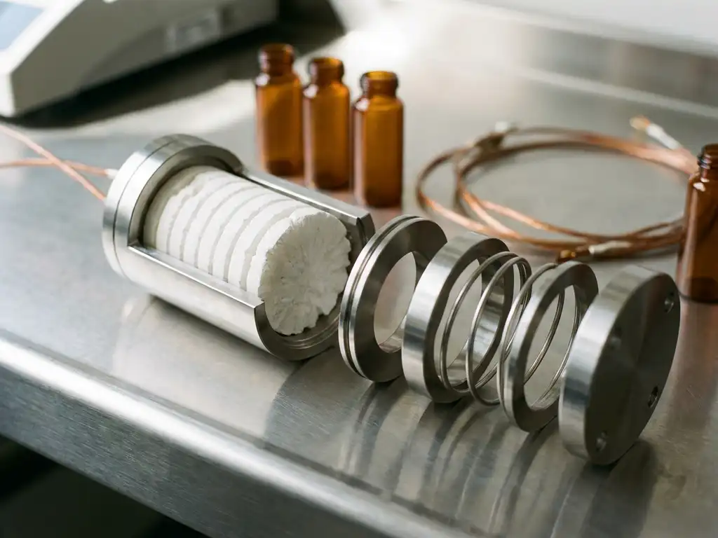
Solid electrolytes impose a fundamentally different set of demands on test cell hardware compared to conventional liquid electrolyte systems. Where liquid electrolytes conform to electrode surfaces and accommodate dimensional changes with relative ease, solid electrolytes are mechanically rigid, chemically sensitive, and highly dependent on interfacial contact quality. Understanding what these materials require — and why conventional hardware falls short — is essential for generating reliable, reproducible data in solid-state battery research.
This article builds from the basic electrochemical distinctions between solid and liquid electrolytes through to the specific hardware design principles that solid-state testing demands. Each section adds a layer of understanding, so that by the end, the connection between material properties and instrument requirements becomes clear.
What makes solid electrolytes fundamentally different from liquid ones
A liquid electrolyte is a solution or ionic liquid that flows freely, fills pores, and maintains continuous ionic contact with both electrodes regardless of minor surface irregularities. A solid electrolyte is a crystalline, glassy, or polymer-based material that conducts ions through a fixed lattice or chain structure, with no ability to conform or redistribute under changing conditions.
This distinction has profound consequences for how ions travel across the electrolyte-electrode interface. In a liquid system, the interface is dynamic and self-healing to some degree. In a solid system, the interface is fixed. Any gap, crack, or delamination between the solid electrolyte and the electrode directly interrupts ionic transport and increases resistance.
The three principal solid electrolyte families each introduce their own complications:
- Oxide-based ceramics (such as garnet-type LLZO or NASICON-type materials) are brittle, require high sintering temperatures, and are sensitive to atmospheric moisture and CO₂.
- Sulphide-based electrolytes (such as LGPS or argyrodite Li₆PS₅Cl) offer higher ionic conductivity but react with moisture to release toxic H₂S, demanding inert atmosphere handling throughout.
- Polymer electrolytes (such as PEO-based systems) are mechanically flexible but require elevated operating temperatures and exhibit significant conductivity dependence on temperature and pressure.
For example, a sulphide pellet exposed to ambient air for even a few minutes during cell assembly can undergo surface degradation that raises interfacial resistance by orders of magnitude — an effect that would be invisible to a researcher unaware of the contamination. The test data would appear to reflect the material’s intrinsic properties when in fact they reflect handling damage.
How solid electrolyte properties shape testing constraints
The physical and chemical properties described above translate directly into constraints on how a test cell must be designed and operated. Three properties in particular drive hardware requirements: ionic conductivity, mechanical stiffness, and atmospheric sensitivity.
Ionic conductivity and the role of contact pressure
Solid electrolytes generally exhibit lower room-temperature ionic conductivity than liquid counterparts, though best-in-class sulphides now approach liquid electrolyte values. More critically, the effective conductivity measured in a test cell depends heavily on the quality of solid-solid contact at the electrode interfaces. Poor contact creates high-resistance zones that dominate electrochemical impedance spectroscopy (EIS) spectra and distort capacity measurements.
Applying controlled uniaxial pressure to the cell stack improves and maintains interfacial contact throughout cycling. This is not optional in solid-state testing — it is a requirement. The pressure must be defined, reproducible, and stable across temperature variations and electrode thickness changes during charge and discharge.
Dimensional changes during cycling
Electrode materials expand and contract as lithium is inserted and extracted. In a liquid electrolyte cell, this is accommodated by the fluid. In a solid electrolyte cell, the rigid electrolyte layer transmits these stresses mechanically. Without controlled pressure compensation, cycling-induced strain can fracture the electrolyte pellet, delaminate interfaces, or generate voids that progressively increase cell resistance. Monitoring these dimensional changes — and controlling the pressure environment — is therefore central to understanding degradation mechanisms.
Atmospheric sensitivity during assembly
Sulphide electrolytes in particular require assembly under inert gas (argon or dry nitrogen) with controlled humidity levels, typically below 0.1 ppm H₂O. Test cell hardware must therefore be compatible with glove box assembly, meaning compact form factors, simple sealing mechanisms, and no components that absorb or release moisture.
Critical hardware requirements for solid electrolyte test cells
Building on the constraints above, solid-state battery testing requires test cells that meet a specific set of structural and functional criteria that differ substantially from those designed for liquid electrolyte research.
- Defined, controllable uniaxial pressure: The cell must apply a known force perpendicular to the electrode stack and maintain it throughout cycling. This rules out spring-loaded designs with poorly characterised force profiles.
- Rigid, dimensionally stable housing: Thermal expansion of the cell body must be minimal and predictable so that applied pressure does not drift with temperature.
- Inert atmosphere compatibility: The cell must be assemblable inside a glove box. Sealing must prevent atmospheric ingress after removal.
- Compatibility with EIS measurement: Electrical connections must support four-point or two-point EIS measurements with minimal parasitic impedance contributions from the hardware itself.
- Dilatometric capability: For research into electrode expansion and electrolyte deformation, the hardware should allow simultaneous measurement of stack thickness changes during electrochemical cycling.
A force test cell addresses the pressure requirement directly by integrating a calibrated spring or mechanical loading mechanism that applies a defined force to the cell stack. This is the foundational hardware choice for solid-state battery testing, as it replaces guesswork about contact quality with a reproducible, quantified parameter.
Where conventional test cells fall short for solid-state research
Conventional test cells introduce a range of practical and technical shortcomings that become especially consequential when working with solid electrolytes. Understanding these limitations explains why purpose-built hardware such as the PAT-Cell-Force and PAT-Cell-Solid from EL-CELL represents a meaningful step forward.
One of the most immediate problems is assembly reliability. Conventional test cells have a high assembly failure rate — studies cite 43%. Even experienced builders achieve only 4 out of 5 working cells on average, while inexperienced researchers fall below 50%. The PAT-Cell-Force and PAT-Cell-Solid standardise and simplify preparation to the point where nearly every cell runs without failure, removing a significant source of wasted time and material.
A second limitation concerns force measurement. Conventional cells do not include a force sensor — only initial pressure is set, and mechanical settling can reduce it over time without any means of detection. EL-CELL cells include an integrated force sensor that tracks applied force throughout the experiment. An optional gas pressure sensor can also be added, enabling researchers to measure force changes caused by gas evolution separately from those caused by mechanical settling — a distinction that is otherwise impossible to make.
Compression homogeneity is a further area where conventional cells underperform. Standard designs compress electrode material inhomogeneously, which introduces variability across the pellet face and complicates data interpretation. The PAT-Solid-Core insert, used in both the PAT-Cell-Force and PAT-Cell-Solid, uses guided plane-parallel tungsten carbide plungers and a dedicated pressing tool to ensure homogeneous compression across the entire electrode area.
Sealing and material choice also matter more than is often appreciated. Conventional cells are typically sealed with O-rings and often use PEEK housings, which absorb significant moisture and require drying at 120°C under vacuum before use. EL-CELL cells use aluminum seals and glass-metal feedthroughs instead of O-rings, and PPS plastic instead of PEEK. PPS absorbs substantially less moisture, reducing both contamination risk and the preparation time needed before glove box assembly.
Finally, plunger durability is a practical concern that compounds over time. Conventional plungers embed electrode particles during use and must be ground or polished between measurements, a process that gradually alters cell geometry and introduces measurement-to-measurement variability. EL-CELL uses tungsten carbide plungers that withstand high mechanical loads without this surface degradation, preserving cell geometry across repeated experiments.
Matching measurement techniques to solid electrolyte chemistries
Different solid electrolyte chemistries require different measurement priorities. The hardware must support the appropriate techniques for the material under investigation.
EIS for interfacial characterisation
EIS is the primary tool for separating bulk electrolyte resistance, grain boundary resistance, and interfacial resistance in solid-state cells. For oxide ceramics with high grain boundary resistance, EIS measurements must extend to high frequencies (above 1 MHz) to resolve the bulk response. For polymer electrolytes, temperature-dependent EIS sweeps are essential because conductivity varies strongly with temperature.
Galvanostatic cycling with controlled pressure
Galvanostatic cycling at defined C-rates (charge/discharge rate relative to capacity) reveals capacity fade, coulombic efficiency (the ratio of charge extracted to charge inserted per cycle), and overpotential evolution. In solid-state cells, overpotential is particularly sensitive to interfacial contact quality, so changes in overpotential during cycling often indicate mechanical degradation rather than purely electrochemical processes.
Operando dilatometry
For researchers studying electrode volume changes and electrolyte deformation simultaneously with electrochemical data, operando dilatometry provides direct measurement of stack thickness as a function of state of charge. This technique is especially valuable for identifying the onset of electrolyte cracking or void formation before it manifests as measurable capacity loss.
Why test cell hardware failures produce misleading solid-state data
A common misconception in solid-state research is that poor data quality reflects poor material quality. In practice, hardware-related artefacts are at least as frequent a source of unreliable data, and they are often more difficult to identify.
Consider the following failure modes and their electrochemical signatures:
- Insufficient or uneven contact pressure: Produces high and variable interfacial resistance, which appears in EIS as a large, poorly defined semicircle. A researcher might incorrectly attribute this to a high-resistance electrolyte material rather than a contact problem.
- Pressure loss during cycling: As electrodes expand and contract, a cell without active pressure compensation loses contact progressively. This manifests as steadily increasing overpotential and apparent capacity fade — symptoms that mimic electrolyte degradation.
- Moisture ingress during or after assembly: Surface degradation of sulphide electrolytes raises interfacial resistance and introduces new EIS features that can be misinterpreted as intrinsic material properties.
- Parasitic impedance from hardware connections: Poorly designed current collectors or contact springs contribute resistance and inductance that distort EIS spectra, particularly at high frequencies where bulk electrolyte responses are measured.
The consequence of these artefacts is not merely inconvenient scatter in data. In a research context, they can lead to incorrect conclusions about material performance, wasted synthesis effort, and results that cannot be reproduced in other laboratories using different hardware. Reproducibility in solid-state battery testing is inseparable from hardware standardisation.
Designing a test cell setup for next-generation solid-state research
Drawing together the concepts covered in the preceding sections, a well-designed solid-state battery testing setup requires decisions at each level: the test cell itself, the pressure control mechanism, the measurement instrumentation, and the environmental controls during assembly.
The starting point is selecting a test cell geometry appropriate for the electrolyte form factor. Pelletised ceramics and sulphides are typically tested in cylindrical cells with flat, parallel current collectors that distribute pressure evenly across the pellet face. Thin-film or polymer electrolytes may require different geometries. In all cases, the cell must allow the application and monitoring of defined uniaxial force throughout the experiment.
Pressure selection is a variable that must be treated as an experimental parameter, not a fixed constant. Different electrolyte materials have different optimal pressure ranges for maximising interfacial contact without fracturing brittle pellets. Systematic pressure variation — combined with EIS measurements at each pressure — allows researchers to identify the optimal operating point for a given material and electrode combination.
The measurement protocol should integrate:
- Initial EIS characterisation before cycling to establish baseline resistance components.
- Galvanostatic cycling at defined C-rates with periodic EIS interruptions to track resistance evolution.
- Operando thickness measurement if electrode volume changes are under investigation.
- Post-mortem analysis protocols that preserve the cell atmosphere during disassembly.
Temperature control is a further variable that is often underestimated. For polymer electrolytes, small temperature deviations significantly alter ionic conductivity and therefore apparent electrochemical performance. For oxide ceramics, temperature affects grain boundary resistance. A test setup that does not control or monitor cell temperature introduces an uncontrolled variable that undermines data reproducibility. The PAT-Cell-Solid integrates mechanical pressure control with compatibility for temperature-controlled environments, addressing both requirements in a single platform.
Finally, documentation of every assembly step — including atmosphere conditions, applied pressure, and torque values for cell closure — is as important as the electrochemical data itself. Solid-state battery testing is highly sensitive to procedural variables, and reproducibility depends on treating assembly as a controlled experimental procedure rather than a routine preparation step.
How EL-Cell GmbH supports solid-state battery testing
EL-Cell GmbH designs test cell hardware specifically for the demands that solid electrolyte materials place on measurement systems. Our product range addresses the core requirements discussed throughout this article:
- The PAT-Cell-Force applies defined, calibrated uniaxial pressure to the cell stack, making contact pressure a controlled and reproducible experimental parameter rather than an unknown variable.
- The PAT-Cell-Solid is designed specifically for pelletised solid electrolyte systems, with a geometry and sealing mechanism suited to glove box assembly and inert atmosphere maintenance.
- The PAT-Cell-Press provides high-force capability for materials requiring elevated stack pressure, with compatibility for temperature-controlled cell chambers.
- The ECD-4-nano electrochemical dilatometer measures electrode and electrolyte thickness changes with sub-5 nm resolution during electrochemical cycling, enabling operando dilatometry alongside standard electrochemical measurements.
- The PAT-Tester-i-16 integrates galvanostatic/potentiostatic cycling with EIS capability across up to 16 channels, providing the measurement platform needed to run systematic, multi-variable solid-state testing programmes.
All components are designed to work together as an interoperable system, which reduces compatibility uncertainties and simplifies the process of building a reproducible solid-state testing workflow. If you are establishing or expanding a solid-state battery research programme and want to discuss which hardware configuration suits your specific electrolyte chemistry and experimental objectives, please contact our technical team directly.
Comments are closed.