


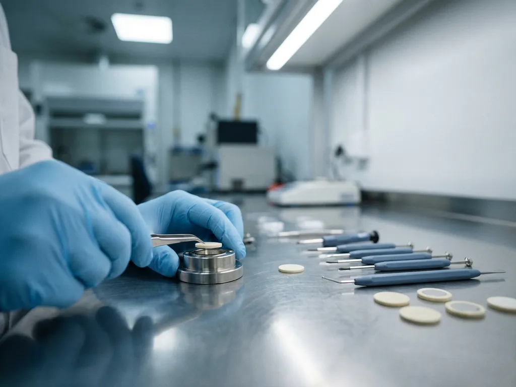
Researchers test solid-state batteries at the cell level using specialised hardware that applies controlled mechanical pressure to the electrode stack, combined with electrochemical methods such as galvanostatic cycling, rate capability testing, and electrochemical impedance spectroscopy (EIS). Unlike liquid electrolyte cells, solid-state systems require intimate interfacial contact between rigid components, which means mechanical and electrochemical variables are deeply coupled. The sections below address the most common questions that arise when setting up and running solid-state cell-level experiments.
What makes solid-state battery testing different from liquid electrolyte cells?
Solid-state battery testing differs from liquid electrolyte cell testing primarily because the electrolyte cannot flow to fill interfacial voids. In a conventional liquid electrolyte cell, the separator and electrolyte conform to electrode surfaces under light compression. In a solid-state cell, ionic transport across the electrolyte-electrode interface depends entirely on physical contact quality, which must be maintained mechanically throughout cycling.
This has several practical consequences for researchers:
- Stack pressure must be defined and controlled as an experimental variable, not simply applied as an assembly step.
- Volume changes in electrodes during cycling directly affect interfacial resistance, so pressure evolution matters over the full cycle life.
- Cell hardware must tolerate higher compressive loads without deforming or short-circuiting.
- Electrolyte fracture and delamination are failure modes with no direct equivalent in liquid electrolyte systems.
These differences mean that protocols developed for liquid electrolyte half cells or coin cells cannot be transferred directly to solid electrolyte cell testing without modification.
What electrochemical methods are used to characterise solid-state cells?
The primary electrochemical methods used to characterise solid-state cells are galvanostatic cycling, rate capability testing, and EIS. Galvanostatic cycling at defined C-rates establishes specific capacity (mAh/g or mAh/cm²), coulombic efficiency, and capacity retention over repeated charge and discharge cycles. EIS is particularly informative for solid-state systems because it can resolve contributions from bulk electrolyte resistance, grain boundary resistance, and interfacial resistance as separate arc features in the Nyquist plot.
Additional methods that are routinely applied include:
- Galvanostatic intermittent titration technique (GITT): Separates thermodynamic overpotential from kinetic overpotential, which is useful when distinguishing bulk ionic transport limitations from interfacial contact resistance.
- Potentiostatic EIS: Applied at defined states of charge to track how interfacial impedance evolves as the electrode undergoes lithiation and delithiation.
- DC polarisation: Used to estimate ionic and electronic conductivity of the solid electrolyte pellet, particularly for oxide and sulphide electrolytes.
- Cyclic voltammetry (CV): Applied at slow scan rates to identify redox features and electrochemical stability windows of the electrolyte under operating conditions.
EIS is especially valuable because changes in interfacial resistance over cycles can serve as an early indicator of contact loss or electrolyte cracking before capacity fade becomes measurable. The PAT-Tester-i-16 supports all of these methods in a single multichannel instrument, combining galvanostat and potentiostat modes with integrated EIS capability.
How is stack pressure controlled during solid-state cell testing?
Stack pressure in solid-state cell testing is controlled by mounting the cell in hardware that applies and maintains a defined uniaxial load on the electrode stack throughout cycling. This is achieved either through spring-loaded mechanisms, pneumatic systems, or dead-weight loading, depending on the required pressure range and whether dynamic pressure tracking is needed. Pressure must remain within a defined window: too low and interfacial contact degrades; too high and the electrolyte pellet fractures.
For research applications, a force-instrumented cell that records stack pressure continuously is preferable to a static compression fixture. Continuous pressure data allows researchers to correlate mechanical changes with electrochemical events, such as a sudden impedance rise coinciding with a pressure drop that indicates delamination. Conventional test cells do not include a force sensor — only the initial pressure is set, and mechanical settling can reduce it over time without any means of detection. The PAT-Cell-Force and PAT-Cell-Solid from EL-CELL address this directly by integrating a calibrated force sensor into the cell body. An optional gas pressure sensor can also be added to measure force changes caused by gas evolution separately from those caused by mechanical settling.
Typical pressure requirements vary by electrolyte class:
- Sulphide electrolytes: Generally require lower pressures (often in the range of a few MPa) because they deform plastically and conform to electrode surfaces relatively easily.
- Oxide electrolytes (LLZO and related garnets): Require higher pressures and often elevated temperatures during assembly to achieve adequate interfacial contact.
- Polymer electrolytes: Moderate pressures at operating temperature; viscoelastic behaviour means pressure relaxation over time must be accounted for.
The PAT-Cell-Force is designed specifically for this purpose, integrating a calibrated force sensor directly into the cell body so that stack pressure is recorded as a function of cycle number alongside the electrochemical data.
What in-situ and operando techniques can be applied to solid-state test cells?
In-situ and operando techniques that can be applied to solid-state test cells include dilatometry, X-ray diffraction (XRD), X-ray tomography, neutron diffraction, and Raman spectroscopy, depending on the cell geometry and the beamline or instrument access available. The key requirement is that the test cell hardware must accommodate the probe without compromising the mechanical boundary conditions that solid-state cells require.
Dilatometry is among the most accessible operando methods for solid-state research. The ECD-4-nano electrochemical dilatometer measures the thickness change of the electrode stack with nanometre resolution during cycling, providing direct information on electrode expansion, electrolyte creep, and contact evolution without requiring synchrotron access.
For diffraction and imaging techniques, cells must be designed with X-ray or neutron transparent windows and low-absorption body materials. Operando XRD tracks structural phase transitions in active materials and can detect electrolyte degradation products as they form. Tomography provides three-dimensional information on void formation, crack propagation, and delamination within the stack.
Operando Raman spectroscopy can be applied to solid-state cells with optical access to monitor local chemical changes at the electrolyte-electrode interface, though signal interpretation is more complex than in liquid electrolyte systems due to the absence of a liquid phase to normalise against.
What cell hardware is required for solid-state battery research?
Solid-state battery research requires cell hardware that provides controlled uniaxial pressure, electrical isolation between components, a defined electrode area, and compatibility with the electrolyte processing conditions, which often include dry-room or inert-atmosphere assembly. Standard coin cells and Swagelok-type cells are frequently used for initial screening but offer limited pressure control and no instrumentation for force or displacement.
Assembly reliability is a significant practical concern with conventional test cells. Studies report an assembly failure rate of around 43% for standard hardware, meaning that even experienced builders achieve only approximately 4 out of every 5 working cells, while less experienced users fall below a 50% success rate. The PAT-Cell-Force and PAT-Cell-Solid from EL-CELL are designed to standardise and simplify preparation so that nearly every assembled cell runs without failure.
Conventional cells also compress electrode material inhomogeneously. Both the PAT-Cell-Force and PAT-Cell-Solid use the PAT-Solid-Core insert, which features guided plane-parallel tungsten carbide plungers and a dedicated pressing tool to ensure homogeneous compression across the electrode area. These tungsten carbide plungers withstand high mechanical loads without embedding particles or degrading over time — a common problem with conventional plungers, which must be ground or polished between measurements, gradually altering cell geometry.
Sealing and material choices also differ significantly. Conventional cells are typically sealed with O-rings and often use PEEK housings, which absorb significant moisture and require drying at 120°C under vacuum before use. EL-CELL cells use aluminum seals and glass-metal feedthroughs instead of O-rings, and PPS plastic instead of PEEK. PPS absorbs considerably less moisture than PEEK, reducing contamination risk and shortening preparation time.
For more rigorous research, dedicated solid-state test cells offer significant advantages:
- Defined and reproducible stack geometry with precise electrode area
- Integrated or attachable force measurement to quantify and control stack pressure
- Compatibility with temperature-controlled environments for elevated-temperature testing
- Modular design allowing different current collector and separator configurations
- Compatibility with external instruments for EIS, dilatometry, or optical access
The PAT-Cell-Solid is purpose-built for solid-state electrolyte research, providing the mechanical and electrochemical boundary conditions needed for reproducible solid-state cell-level testing. For experiments requiring simultaneous force and electrochemical data, the PAT-Cell-Force extends this capability with integrated load sensing.
What are the most common failure modes observed during solid-state cell testing?
The most common failure modes in solid-state cell testing are interfacial delamination, electrolyte cracking, lithium dendrite penetration through the solid electrolyte, and active material particle fracture. Each of these failure modes has a distinct electrochemical signature, which is why combining cycling data with impedance measurements and operando diagnostics is standard practice in rigorous solid-state research.
The main failure modes and their observable indicators are:
- Interfacial delamination: Progressive increase in interfacial resistance visible in EIS; often correlates with a drop in stack pressure in force-instrumented cells. Caused by volume mismatch between electrode and electrolyte during cycling.
- Electrolyte cracking: Sudden increase in cell resistance or internal short circuit. More common in brittle oxide electrolytes under excessive stack pressure or thermal cycling.
- Lithium dendrite penetration: Manifests as a soft short circuit, characterised by a gradual decrease in open-circuit voltage and anomalous self-discharge. Current density, stack pressure, and electrolyte density all influence the onset of this failure mode.
- Active material particle fracture: Capacity fade without a corresponding increase in interfacial resistance; often identified by post-mortem scanning electron microscopy (SEM) rather than electrochemical data alone.
- Electrolyte decomposition: Irreversible capacity loss and growth of new impedance features in EIS spectra, particularly at high voltages or in systems where the electrolyte electrochemical stability window is exceeded.
Distinguishing between these failure modes requires careful experimental design, including controlled pressure, well-defined electrode areas, and periodic EIS measurements throughout the cycle life rather than only at the beginning and end of the test.
How EL-Cell GmbH supports solid-state battery research
EL-Cell GmbH develops and manufactures the hardware, instrumentation, and software that researchers need to conduct reproducible solid-state battery cell-level testing. Our product ecosystem is built around the PAT Series, which is designed so that mechanical, electrochemical, and diagnostic measurements are captured from the same cell under consistent boundary conditions.
Key capabilities we offer for solid-state research include:
- PAT-Cell-Solid: A dedicated test cell for solid electrolyte systems with defined electrode geometry and compatibility with inert-atmosphere assembly.
- PAT-Cell-Force: Integrates a calibrated force sensor to record stack pressure continuously alongside electrochemical data, enabling direct correlation between mechanical and electrochemical events.
- ECD-4-nano: A high-resolution electrochemical dilatometer that quantifies electrode stack thickness changes with a resolution of better than 5 nm, providing operando mechanical data without synchrotron access.
- PAT-Tester-i-16: A multichannel battery tester with integrated EIS capability, temperature-controlled cell chamber, and docking station, supporting up to 16 channels with potentiostat and galvanostat modes.
- EL-Software: Data acquisition and analysis software designed to work across the PAT Series, allowing EIS, cycling, and force data to be recorded and analysed within a single interoperable workflow.
If you are setting up a solid-state research programme or looking to improve the reproducibility of your existing cell-level tests, contact EL-Cell GmbH to discuss the right configuration for your experimental requirements.
Comments are closed.