


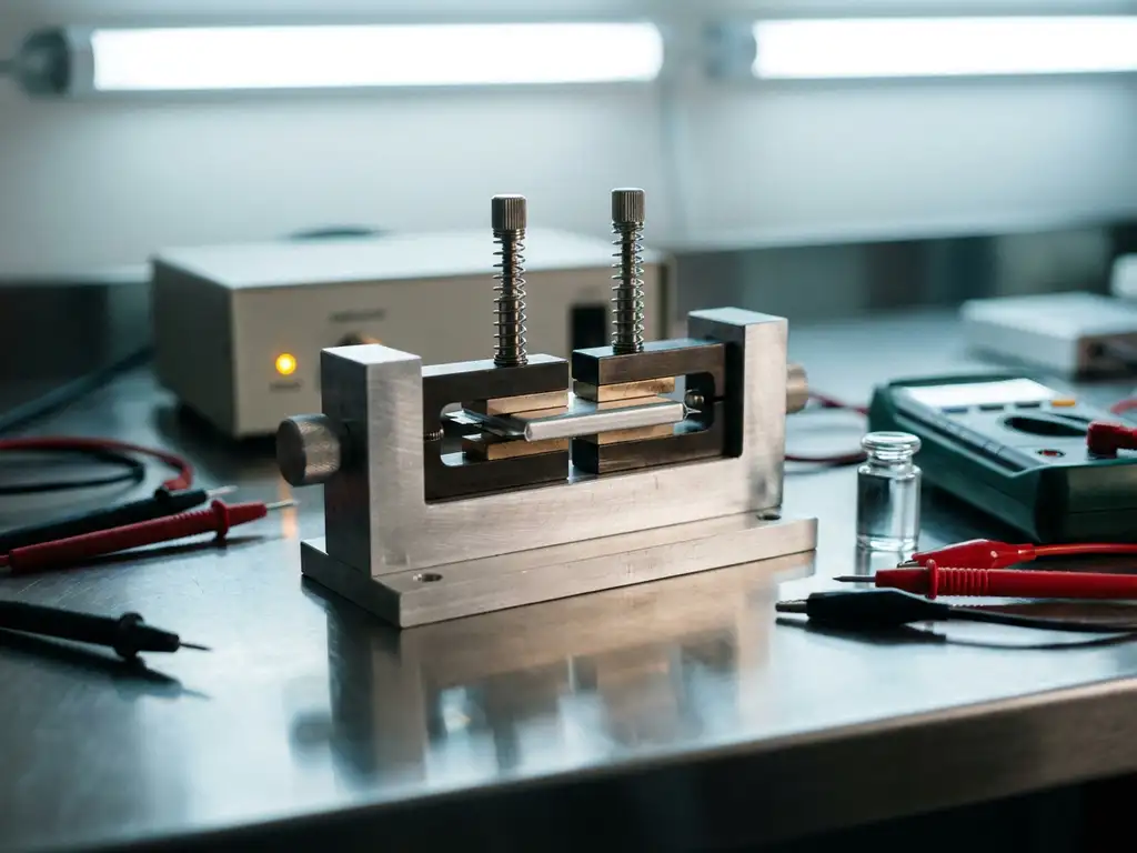
Fixture limitations skew solid-state battery test results when stack pressure is inconsistent, contact resistance is uncontrolled, or cell geometry introduces artefacts that mimic material behaviour. These errors are particularly difficult to detect because they produce data that looks plausible — capacity fade, impedance growth, and voltage polarisation all have legitimate electrochemical causes. The sections below address the most common fixture-related failure modes and how to distinguish them from genuine material responses.
What fixture variables most commonly distort solid-state battery measurements?
The fixture variables that most commonly distort solid-state battery measurements are stack pressure, current collector contact quality, temperature uniformity, and cell alignment. Each of these can independently introduce artefacts, and in combination they can make a poorly performing fixture indistinguishable from a poorly performing electrolyte or electrode material.
Solid-state cells are uniquely sensitive to mechanical boundary conditions because the electrolyte is a rigid solid rather than a liquid that conforms to surfaces. Any gap, misalignment, or pressure non-uniformity at the electrode-electrolyte interface translates directly into measurable electrochemical deviation. The most frequently encountered distortion sources include:
- Stack pressure: Too little pressure leaves interfacial voids; too much can crack brittle oxide or sulphide electrolytes
- Current collector contact: Uneven or oxidised contact surfaces introduce parasitic resistance that appears in impedance spectra
- Thermal gradients: Non-uniform temperature across the cell area produces spatially variable ionic conductivity
- Cell alignment: Off-centre stacking creates edge effects and uneven current distribution
- Torque inconsistency: Manual assembly without controlled torque leads to irreproducible pressure between repeat experiments
Because these variables interact, isolating a single cause requires systematic control of each one independently before drawing conclusions about the material under test.
How does stack pressure affect solid-state battery test data?
Stack pressure directly controls the quality of solid-solid interfaces throughout the cell stack, and even modest pressure variation produces measurable changes in interfacial impedance, capacity utilisation, and cycling stability. In solid-state cells, pressure is not merely a mechanical consideration — it is an electrochemical variable that must be treated with the same rigour as temperature or current density.
At insufficient pressure, interfacial voids between the electrode and solid electrolyte increase the effective ionic resistance at that boundary. This manifests as a large semicircle in electrochemical impedance spectroscopy (EIS) at intermediate frequencies, which can be misread as a high grain-boundary resistance intrinsic to the electrolyte material. As pressure increases, this semicircle typically collapses — confirming the artefact is mechanical rather than chemical.
Excessive pressure introduces a different set of problems. Brittle electrolyte materials, particularly sulphide-based systems, can develop microcracks under loads that exceed their fracture threshold. These cracks increase electronic shorting pathways and reduce the effective ionic cross-section, producing erratic capacity values and elevated self-discharge. Neither outcome reflects the material’s intrinsic properties.
Reproducible research therefore requires a test cell capable of applying and maintaining a defined, measurable uniaxial force throughout cycling. The PAT-Cell-Force is designed precisely for this purpose, providing direct force measurement rather than inferred torque values. Conventional cells do not include a force sensor — only initial pressure is read at assembly, and mechanical settling can reduce it over time without detection. The PAT-Cell-Force addresses this with an integrated force sensor, so the actual force on the stack is known throughout the experiment. An optional gas pressure sensor can also be added, allowing force changes caused by gas evolution to be measured separately from purely mechanical ones. Cells that rely on spring washers or fixed-torque bolts without direct force measurement cannot confirm what pressure the stack actually experienced, particularly as electrode volume changes during cycling alter the mechanical state of the assembly.
What are the signs that contact resistance is corrupting your EIS results?
Contact resistance corruption in EIS results is indicated by a high-frequency intercept that shifts between measurements without any change to the material, a depressed or flattened high-frequency semicircle, and impedance values that change when the cell is disassembled and reassembled without altering the electrodes or electrolyte.
In a well-assembled solid-state cell, the high-frequency real-axis intercept in a Nyquist plot represents the bulk ionic resistance of the electrolyte plus the electronic resistance of the current collectors and leads. If this value is larger than expected based on the electrolyte’s known conductivity, or if it varies between nominally identical cells, parasitic contact resistance is the most likely explanation.
Additional diagnostic indicators include:
- Impedance that decreases after applying additional mechanical pressure to the cell housing
- A high-frequency semicircle that cannot be assigned to a known electrochemical process and disappears when contact surfaces are cleaned or replaced
- Asymmetric impedance response between charge and discharge half-cycles that correlates with current collector condition rather than state of charge
- Scatter in EIS data that correlates with the assembly operator rather than with the electrolyte batch
Oxidised current collector surfaces are a common and underappreciated source of contact resistance in research environments. Gold-plated or stainless steel current collectors maintained in inert atmosphere assembly conditions substantially reduce this variable. If EIS measurements are taken outside a controlled environment, surface contamination between assembly and measurement can introduce resistance that is attributed incorrectly to the electrolyte.
How can you tell if capacity loss is from the material or the test setup?
Capacity loss originating from the test setup rather than the material can be identified by comparing cells assembled under different fixture conditions but using identical electrode and electrolyte batches. If the capacity loss rate correlates with fixture variables — pressure, contact quality, temperature — rather than with material composition, the setup is the primary source of degradation.
Several diagnostic approaches help isolate the origin of capacity fade:
- Reassembly test: Disassemble a cell showing capacity loss, inspect the components, and reassemble with fresh current collectors. If capacity recovers substantially, the loss was contact-related rather than material-related.
- Pressure variation series: Cycle nominally identical cells at different defined stack pressures. Capacity that varies systematically with pressure indicates a fixture-dominated response.
- Coulombic efficiency tracking: Low coulombic efficiency in early cycles that stabilises is consistent with SEI (solid electrolyte interphase) formation. Coulombic efficiency that remains low and erratic across many cycles is more consistent with intermittent contact loss or micro-shorting through cracked electrolyte.
- Post-mortem analysis: Physical inspection of the electrolyte pellet for cracking, and of electrode surfaces for non-uniform contact marks, directly reveals mechanical failure modes.
A critical distinction is between gradual, smooth capacity fade — which is characteristic of material degradation mechanisms such as lithium dendrite growth or electrolyte decomposition — and stepped or irregular capacity loss, which more commonly reflects mechanical instability in the fixture.
What test cell design features minimise fixture-related artefacts?
Test cell designs that minimise fixture-related artefacts in solid-state battery testing share several key features: defined and measurable uniaxial stack pressure, chemically inert and low-resistance current collectors, precise cell alignment guides, hermetic sealing compatible with reactive electrolyte materials, and thermal uniformity across the electrode area.
Pressure control is the single most impactful design feature for solid-state work. Cells that incorporate a calibrated spring mechanism or an integrated load cell allow the researcher to specify and verify the force applied to the stack, rather than inferring it from bolt torque. This is essential for comparing results between laboratories or between different researchers within the same group.
Beyond pressure, the following design characteristics reduce systematic error:
- Gold-plated or otherwise protected current collector surfaces to minimise contact resistance and oxidation
- Precision-machined alignment features that ensure coaxial stacking of all layers
- Electrochemically inert cell body materials compatible with sulphide and oxide electrolyte chemistries
- Sealed designs that prevent atmospheric moisture ingress during long-term cycling experiments
- Geometry that accommodates electrode thickness changes without altering the applied pressure outside the intended range
- Homogeneous compression of electrode material — the PAT-Solid-Core insert, used in both the PAT-Cell-Force and the PAT-Cell-Solid, achieves this through guided plane-parallel tungsten carbide plungers and a dedicated pressing tool, in contrast to conventional cells where compression is often inhomogeneous
- Robust plunger materials — tungsten carbide withstands high mechanical loads without embedding particles into the plunger surface, which is a known problem with softer materials that gradually alters cell geometry and requires grinding or polishing between measurements
- Aluminium seals and glass-metal feedthroughs rather than O-rings, and PPS plastic rather than PEEK — PPS absorbs significantly less moisture than PEEK, which requires drying at 120°C under vacuum and poses a greater contamination risk during cell preparation
For researchers working with force test cells such as the PAT-Cell-Force or the PAT-Cell-Solid, the ability to monitor and control stack pressure throughout the experiment — not only at assembly — is a meaningful improvement over fixed-geometry designs.
When should you suspect the fixture rather than the electrolyte?
The fixture should be the primary suspect when unexpected results are irreproducible across nominally identical cells, when performance varies with the assembly operator, when impedance or capacity changes are not accompanied by any expected chemical signature, or when results improve after modifying the mechanical assembly without changing any electrochemical component.
A useful diagnostic heuristic is to ask whether the observation is physically consistent with what the material can actually do. If impedance values are an order of magnitude larger than the electrolyte’s known bulk conductivity would predict, the excess resistance is almost certainly mechanical in origin. If capacity is substantially lower than the theoretical value for the electrode material at the applied C-rate, and the shortfall cannot be explained by known electrochemical limitations, fixture contact quality is a more parsimonious explanation than an uncharacterised material failure.
Specific scenarios that should redirect suspicion toward the fixture include:
- Results that improve monotonically as stack pressure increases, up to a plateau — indicating that full contact was not achieved at lower pressures
- Impedance that changes between measurements taken on the same cell without any cycling in between
- Capacity values that scatter widely across a batch of cells made from the same materials
- Voltage profiles that show unexpected plateaus or polarisation spikes that disappear after reassembly
- Performance that degrades faster in one laboratory than in another using the same electrolyte composition
Assembly failure rate is another dimension of fixture-related error that is easy to overlook. Studies on conventional test cells cite an assembly failure rate of around 43% — even experienced builders achieve only 4 out of 5 working cells, and inexperienced ones fall below 50%. The PAT-Cell-Force and PAT-Cell-Solid from EL-CELL are designed to standardise and simplify preparation so that nearly every cell runs without failure, which also reduces the risk of attributing assembly-related failures to material problems.
Establishing a baseline with a well-characterised reference material — one whose electrochemical behaviour is already well understood — is a practical way to calibrate a new fixture and confirm that it is not introducing systematic error before committing to a series of experiments on novel materials. EL-Cell’s Application Laboratory can support this process by providing measurement services on well-defined reference systems.
How EL-Cell GmbH helps with solid-state battery testing
EL-Cell GmbH designs test cells specifically for the mechanical and electrochemical demands of solid-state battery research. Our PAT Series product range addresses the fixture variables described throughout this article with hardware engineered to give researchers control over the conditions that matter most.
- The PAT-Cell-Force applies and maintains a defined uniaxial stack pressure throughout cycling, with an integrated force sensor providing direct force measurement rather than inferred torque values — eliminating one of the most common sources of irreproducibility in solid-state testing. An optional gas pressure sensor allows force changes due to gas evolution to be tracked independently of mechanical settling.
- The PAT-Cell-Solid is designed specifically for pelletised solid electrolyte systems, with geometry and materials selected to minimise contact resistance and accommodate the mechanical properties of oxide and sulphide electrolytes. Both the PAT-Cell-Force and PAT-Cell-Solid use the PAT-Solid-Core insert with guided plane-parallel tungsten carbide plungers and a dedicated pressing tool for homogeneous compression.
- The PAT-Cell-Press provides controlled uniaxial pressure for pouch-format and pressed-pellet assemblies, supporting systematic pressure variation studies
- All PAT Series cells are compatible with the PAT-Tester-i-16, which integrates EIS capability directly into the cycling platform — allowing impedance measurements without reconnecting cables or disturbing the mechanical state of the cell
- Our complete ecosystem approach means current collectors, sealing components, and cell hardware are designed to work together, reducing the risk of compatibility-related artefacts from mixed-source components
If you are working on solid-state electrolyte characterisation or electrode-electrolyte interface studies and need to verify that your test setup is not limiting your data quality, we are glad to discuss your experimental requirements. Contact our applications team or visit our PAT Series overview to review the specifications in detail.
Comments are closed.