


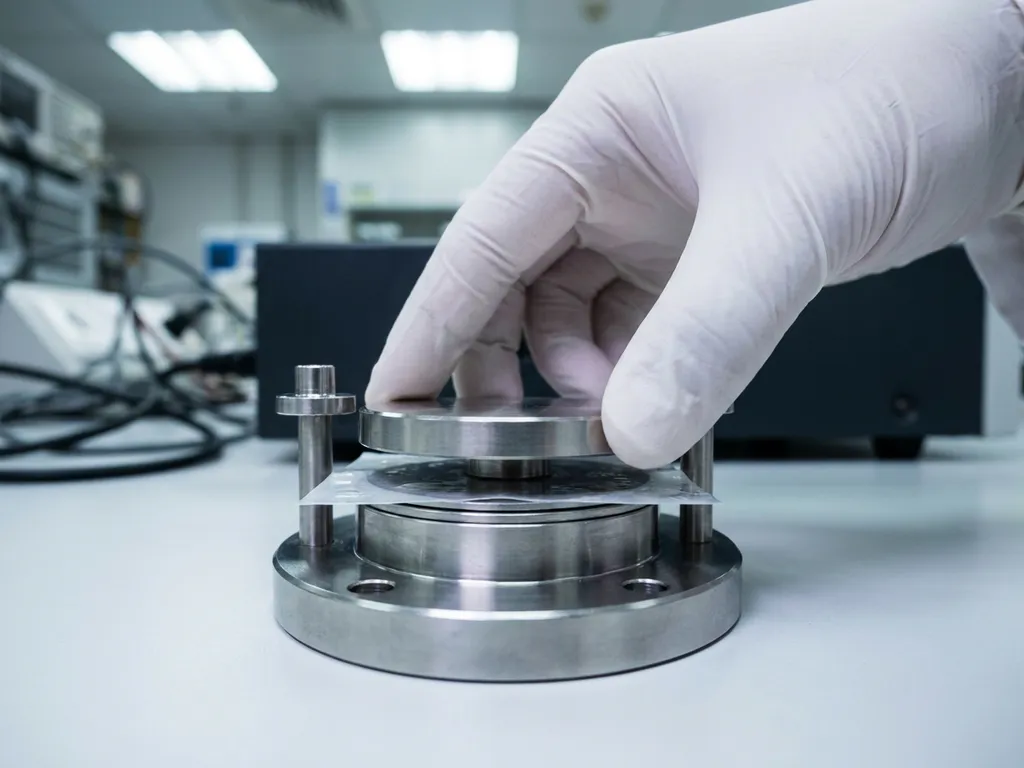
Electrode-electrolyte contact quality is one of the most consequential variables in any electrochemical test cell, yet it receives far less attention than electrode formulation or cycling protocol. Poor contact at the interface introduces artefacts that are difficult to distinguish from genuine material behaviour, leading to data that cannot be reproduced or published with confidence. This article builds from first principles through to practical assembly guidance, giving researchers a systematic framework for evaluating and improving contact quality in their test cells.
What is electrode-electrolyte contact and why does it matter?
Electrode-electrolyte contact refers to the physical and chemical quality of the interface between an electrode material and the electrolyte that surrounds or permeates it. At this interface, ionic charge carriers must transfer between the electrolyte phase and the electronic conductor of the electrode, a process that governs every electrochemical measurement made in the cell.
The interface is not a simple two-dimensional boundary. In porous electrodes, it extends throughout the entire electrode volume, meaning that the quality of contact is a function of electrolyte wetting depth, electrode surface roughness, and the mechanical pressure holding components together. In solid-state systems, where a liquid electrolyte is replaced by a solid ionic conductor, the contact challenge becomes even more pronounced because the electrolyte cannot flow to fill voids.
For example, consider a half-cell assembled with a partially wetted electrode. Regions of the active material that have no electrolyte contact are electrochemically inactive, effectively reducing the usable electrode area without any visible indication during assembly. The measured specific capacity in mAh/g will appear lower than the true material value, and the researcher may incorrectly attribute the deficit to the material itself.
How poor contact propagates error through your measurements
Contact deficiencies do not produce a single, identifiable error signal. Instead, they propagate through multiple measurement parameters simultaneously, making root-cause diagnosis difficult after the fact.
Incomplete wetting increases the effective interfacial impedance. When electrochemical impedance spectroscopy (EIS) is performed, this manifests as an artificially enlarged charge-transfer resistance semicircle. A researcher comparing two electrode formulations using EIS may conclude that one material has inherently slower kinetics, when the true cause is uneven electrolyte distribution across the electrode surface.
Under galvanostatic cycling, poor contact creates localised current density gradients. Areas with good contact carry a disproportionate share of the applied current, accelerating local degradation and producing capacity fade that appears to reflect the material’s intrinsic cycling stability. Coulombic efficiency measurements are particularly sensitive to this effect, because parasitic reactions at stressed interfacial regions consume charge that is never recovered.
- Elevated and irreproducible internal resistance values
- Artificially depressed specific capacity in mAh/g or mAh/cm²
- Premature capacity fade attributed incorrectly to material degradation
- Distorted EIS spectra with inflated charge-transfer resistance
- High cell-to-cell variability that undermines statistical confidence
Key factors that govern contact quality in lab test cells
Understanding which physical variables control contact quality allows researchers to intervene deliberately rather than rely on chance. Four factors dominate in most lab-scale test cells.
Stack pressure
Applied stack pressure determines how intimately the electrode, separator, and electrolyte are held together. Insufficient pressure leaves gaps, particularly after the separator absorbs electrolyte and swells. Excessive pressure can close electrode pores, restricting ionic transport. In solid-state battery testing, stack pressure is critical because solid electrolytes cannot conform to surface irregularities without mechanical force. Force test cells are specifically designed to apply and monitor defined, reproducible stack pressures throughout cycling, which is why they are a standard tool for solid-state battery testing where contact loss under volume change is a primary failure mode.
Electrolyte wetting time
Liquid electrolytes require time to penetrate the porous structure of a composite electrode. Assembling a cell and beginning cycling immediately is a common source of irreproducible data. Wetting kinetics depend on electrolyte viscosity, electrode porosity, and the surface energy of the active material and binder. Allowing sufficient rest time before the first charge or discharge cycle gives the electrolyte time to equilibrate throughout the electrode volume.
Surface preparation and cleanliness
Oxide layers, adsorbed moisture, and particulate contamination on electrode surfaces all increase interfacial resistance. Electrode preparation in a controlled atmosphere, typically an argon-filled glovebox, prevents adventitious oxidation and moisture uptake that would otherwise compromise the interface before the cell is even closed.
Separator integrity and placement
A misaligned or damaged separator creates regions of direct electronic contact between electrodes, causing local short circuits. Even a separator that appears intact may have pinholes that produce soft shorts, detectable only through careful open-circuit voltage monitoring after assembly.
How to assess contact quality before and during testing
Contact quality can be evaluated at several stages of the experimental workflow, and early detection prevents wasted cycling time on fundamentally compromised cells.
Before cycling begins, a brief EIS measurement at open-circuit voltage provides a baseline impedance spectrum. The high-frequency intercept with the real axis gives the ohmic resistance of the cell, which reflects contact and electrolyte resistance combined. A value that is unexpectedly high, or inconsistent across nominally identical cells, signals a contact problem before any capacity data has been collected.
Monitoring the open-circuit voltage during the wetting period is a simple but informative check. A stable open-circuit voltage after electrolyte addition indicates that the cell is equilibrating correctly. Rapid drift or an unusually low open-circuit voltage suggests either a soft short or incomplete electrolyte distribution.
During cycling, tracking the evolution of internal resistance through periodic EIS measurements or direct current pulse methods reveals whether contact is degrading. In electrode materials that undergo significant volume change during lithiation, contact loss is progressive and will appear as a gradual increase in impedance over successive cycles. The ECD-4-nano electrochemical dilatometer allows researchers to directly correlate volume change with electrochemical response, making it easier to identify when dimensional changes are contributing to contact degradation.
Common assembly mistakes that compromise the interface
The majority of contact-quality problems in research cells originate during assembly rather than from the materials themselves. Recognising these mistakes is the first step to eliminating them.
- Insufficient electrolyte volume: Using too little electrolyte leaves portions of the electrode dry. The minimum volume needed depends on electrode porosity and separator thickness, and should be determined empirically for each electrode formulation.
- Immediate cycling after assembly: Starting a cycling protocol before the electrolyte has fully wetted the electrode stack compresses the wetting process into the first charge cycle, distorting first-cycle coulombic efficiency and Solid Electrolyte Interphase (SEI) formation data.
- Uneven torque on cell fasteners: In coin cells and custom test cells, uneven mechanical closure creates non-uniform stack pressure. Using a torque wrench or a defined closure procedure eliminates this variable.
- Electrode calendering inconsistency: Variations in electrode thickness across a batch change the stack compression achieved at a given closure torque, introducing cell-to-cell variability that is difficult to decouple from material variability.
- Glovebox moisture ingress: Even brief exposure to elevated moisture levels during assembly can hydrate the electrolyte salt or oxidise lithium metal reference electrodes, both of which alter the interfacial chemistry before the first measurement.
Build a contact-quality checklist for reproducible results
A systematic pre-assembly and post-assembly checklist converts the principles above into a repeatable laboratory procedure. The goal is to eliminate contact quality as a source of variability before attributing differences between cells to material properties.
Building on the factors covered in the sections above, the following checklist addresses each critical control point in sequence.
- Electrode characterisation: Measure electrode thickness and mass loading for every electrode before assembly. Reject electrodes that fall outside a defined tolerance to ensure consistent stack compression.
- Atmosphere control: Confirm glovebox oxygen and moisture levels are within specification before beginning assembly. Log these values alongside the cell identifier.
- Electrolyte volume: Dispense electrolyte gravimetrically or with a calibrated micropipette. Record the volume added for each cell.
- Wetting rest period: Allow a defined rest period at open-circuit before beginning any electrochemical measurement. The duration should be validated for each electrode system.
- Baseline EIS measurement: Record an EIS spectrum at open-circuit voltage before the first cycle. Compare the ohmic resistance across all cells in a batch and flag outliers.
- Open-circuit voltage check: Confirm that the open-circuit voltage is within the expected range for the electrode chemistry and is stable over a short observation window.
- Stack pressure verification: For cells where pressure is controlled mechanically, confirm the applied force before sealing. For solid-state cells, verify that the target pressure is maintained throughout the experiment.
Applying this checklist consistently across a batch reduces the proportion of cells that must be discarded due to assembly-related artefacts, and makes it far easier to identify genuine material behaviour in the data that remains. If you would prefer to have contact quality assessed by specialists, the EL-Cell Application Laboratory offers measurement services using the full PAT Series hardware and software ecosystem.
How EL-Cell GmbH supports electrode-electrolyte contact quality in research
EL-Cell GmbH designs test cells and instrumentation specifically to give researchers control over the variables that determine contact quality. Several products in our portfolio address the challenges described throughout this article.
Assembly reliability is a significant practical concern with conventional test cell designs. Studies report an assembly failure rate of around 43% for standard cells, and even experienced researchers typically achieve only four out of five working cells. For less experienced builders, success rates can fall below 50%. The PAT-Cell-Force and PAT-Cell-Solid from EL-CELL standardize and simplify the preparation process so that nearly every assembled cell runs without failure.
Conventional test cells also lack any means of monitoring force during cycling. Only the initial pressure is set at assembly, and mechanical settling can reduce it over time without any indication to the researcher. Both the PAT-Cell-Force and PAT-Cell-Solid include an integrated force sensor that tracks pressure continuously throughout the experiment. An optional gas pressure sensor can be added to distinguish force changes caused by gas evolution from those arising from mechanical sources — a distinction that is impossible to make with conventional hardware.
Homogeneous compression of the electrode stack is another area where conventional cells fall short. Standard designs compress electrode material inhomogeneously, introducing variability in contact quality across the electrode area. Both the PAT-Cell-Force and PAT-Cell-Solid use the PAT-Solid-Core insert, which employs guided plane-parallel tungsten carbide plungers and a dedicated pressing tool to ensure homogeneous compression across the entire electrode surface.
The choice of materials in the cell housing also affects preparation time and contamination risk. Conventional cells are commonly sealed with O-rings and built with PEEK housings. PEEK absorbs significant moisture and must be dried at 120°C under vacuum before use. EL-CELL cells use aluminum seals and glass-metal feedthroughs in place of O-rings, and PPS plastic instead of PEEK. Because PPS absorbs considerably less moisture than PEEK, contamination risk is reduced and preparation time is shortened.
Finally, the tungsten carbide plungers used in EL-CELL cells offer a durability advantage over conventional alternatives. Standard plungers embed particles during use and must be ground or polished between measurements, gradually altering the cell geometry over time. Tungsten carbide withstands high mechanical loads without this form of degradation, preserving the cell geometry across many measurement cycles.
- The PAT-Cell-Force applies a defined, continuously monitored stack pressure throughout cycling, making it the appropriate choice whenever electrode volume change or solid electrolyte contact loss is under investigation.
- The PAT-Cell-Solid is engineered for solid-state battery testing, with a geometry that accommodates the high pressures required to maintain contact between solid electrolyte and electrode layers.
- The PAT-Cell provides a versatile platform for liquid electrolyte systems, with a well-defined stack geometry that supports reproducible assembly across batches.
- The PAT-Tester-i-16 integrates galvanostatic cycling with EIS capability across up to 16 channels, enabling the baseline and in-cycle impedance measurements described in the assessment section above without requiring a separate instrument.
- Our complete PAT Series ecosystem ensures that cell hardware, tester, and software are fully compatible, removing instrument mismatch as a source of measurement uncertainty.
If you are developing a testing protocol for a new electrode system or transitioning to solid-state cell formats, contact us to discuss which cell configuration and measurement approach best fits your experimental requirements.
Comments are closed.