


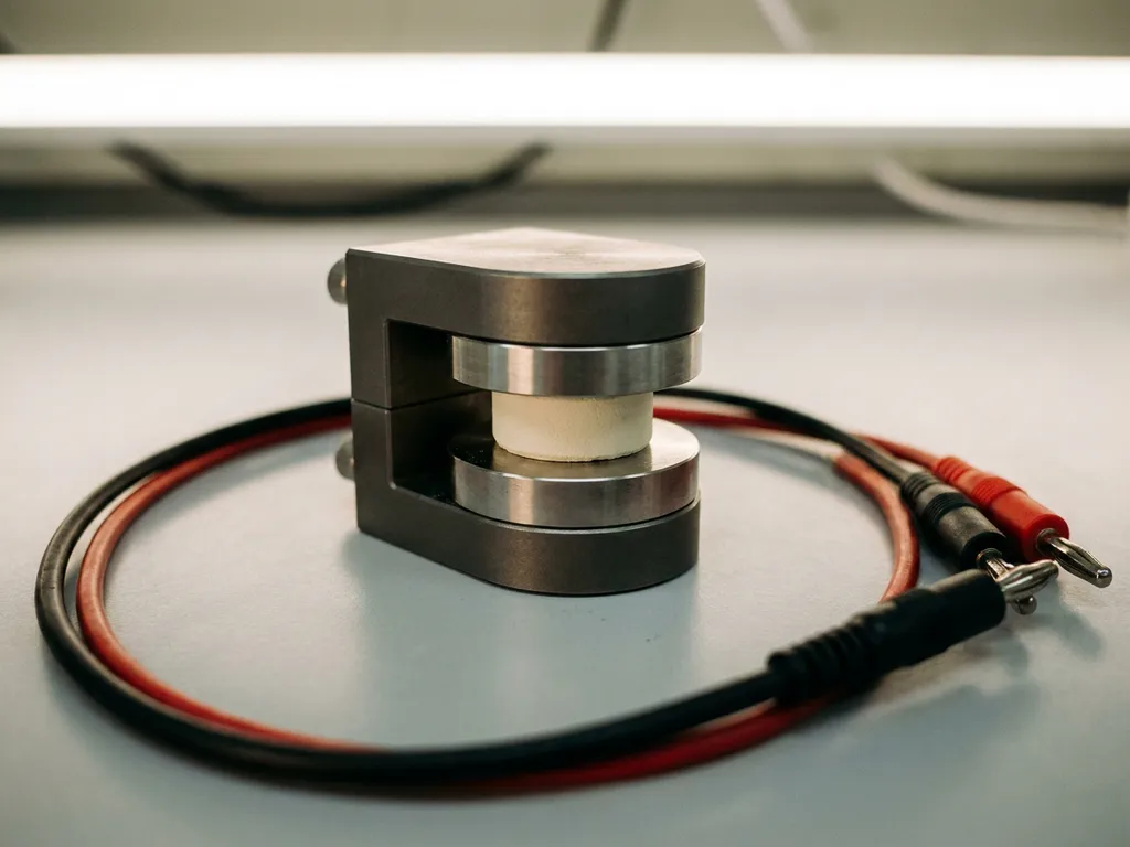
Ionic conductivity in a solid-state electrolyte is most reliably measured using electrochemical impedance spectroscopy (EIS), which separates resistive contributions from the bulk material, grain boundaries, and electrode interfaces. For complete characterisation, EIS is typically combined with appropriate cell geometry, controlled temperature conditions, and blocking or non-blocking electrodes depending on the measurement objective. The sections below address the key practical and conceptual questions that arise when setting up and interpreting ionic conductivity measurements.
What methods are used to measure ionic conductivity in solid electrolytes?
Electrochemical impedance spectroscopy (EIS) is the primary method for measuring ionic conductivity in solid electrolytes, offering the ability to deconvolute contributions from the bulk material, grain boundaries, and electrode interfaces in a single measurement. For a material with ionic conductivity in the range typical of solid electrolytes, EIS provides a frequency-resolved view of ion transport that no DC technique can match.
Beyond EIS, several complementary approaches are used depending on the material class and the specific conductivity regime under investigation:
- DC polarisation methods — used to estimate electronic conductivity and, by subtraction, isolate the ionic component. Particularly relevant for mixed ionic-electronic conductors.
- Hebb-Wagner polarisation — a DC technique employing a blocking electrode to suppress electronic current and isolate the ionic transference number.
- Time-domain relaxation methods — occasionally applied to polymeric or composite solid electrolytes where the impedance response is broad and difficult to resolve spectrally.
For most inorganic solid electrolytes — oxides, sulphides, halides — EIS remains the standard. DC methods are useful as cross-checks, particularly when the electronic conductivity of the material is non-negligible.
How does electrochemical impedance spectroscopy measure ionic conductivity?
EIS measures ionic conductivity by applying a small-amplitude sinusoidal voltage across the sample over a range of frequencies and recording the resulting current response. The complex impedance spectrum is then fitted to an equivalent circuit model, from which the bulk resistance of the electrolyte is extracted. Ionic conductivity is calculated from this resistance using the sample geometry.
The typical equivalent circuit for a polycrystalline solid electrolyte consists of parallel RC elements in series, each representing a distinct physical process:
- A high-frequency arc corresponding to bulk (lattice) ion transport
- A mid-frequency arc corresponding to grain boundary resistance
- A low-frequency feature corresponding to electrode polarisation
Once the bulk resistance Rb is determined from the Nyquist plot, ionic conductivity is calculated as:
σ = L / (Rb × A)
where L is the sample thickness and A is the electrode contact area. The accuracy of this calculation depends critically on the precision with which the cell geometry is defined — a point that directly motivates the use of well-characterised test cells with defined contact areas.
What cell geometry and electrode setup do you need for EIS testing?
For EIS-based ionic conductivity measurement, the cell geometry must be precisely defined: a pellet or thin-film electrolyte of known thickness and cross-sectional area is sandwiched between two electrodes under controlled and reproducible contact pressure. Deviations in geometry directly propagate into errors in the calculated conductivity value.
Electrode choice depends on whether the measurement uses blocking or non-blocking contacts:
- Blocking electrodes (e.g. sputtered gold, platinum, or stainless steel) do not allow ion transfer across the interface. They are used when only the total ionic conductivity is needed and the low-frequency electrode arc is not of interest.
- Non-blocking (reversible) electrodes allow ion exchange and are required when measuring transference numbers or when the electrode interface is itself under investigation.
Contact pressure is a significant variable, particularly for sulphide-based solid electrolytes, which are mechanically soft and deform under load. A spring-loaded or pneumatic cell that applies a defined and reproducible stack pressure is therefore preferred over a hand-tightened assembly. The PAT-Cell-Solid is designed specifically for solid electrolyte testing with controlled uniaxial pressure, making it well suited to this type of measurement. Importantly, both the PAT-Cell-Force and PAT-Cell-Solid from EL-CELL incorporate the PAT-Solid-Core insert, which uses guided plane-parallel tungsten carbide plungers and a dedicated pressing tool to ensure homogeneous compression of the electrode material — something conventional test cells, which compress electrode material inhomogeneously, cannot reliably achieve.
For pellet-based samples, a two-electrode configuration is standard. Four-electrode arrangements are used in specialised setups where contact resistance must be independently characterised, though these are less common for routine solid electrolyte screening.
How do temperature and atmosphere affect ionic conductivity measurements?
Ionic conductivity in solid electrolytes is strongly temperature-dependent, following Arrhenius behaviour in most inorganic materials. Measuring conductivity across a temperature range allows the activation energy for ion transport to be extracted, which is a more informative materials descriptor than a single room-temperature value.
The practical implications for measurement are significant:
- Temperature must be controlled and stable during each EIS acquisition. Drift of even a few degrees Celsius during a long frequency sweep can distort the impedance spectrum.
- Measurements should be recorded at thermal equilibrium, not during active heating or cooling ramps.
- The temperature range selected should reflect the intended application — room temperature for ambient-condition devices, elevated temperatures for solid oxide or high-temperature ceramic electrolytes.
Atmosphere control is equally critical, particularly for sulphide-based electrolytes such as Li6PS5Cl (argyrodite) or Li10GeP2S12 (LGPS), which react rapidly with moisture and oxygen. All sample preparation and cell assembly for these materials must be performed in an inert atmosphere (argon or dry nitrogen), and the test cell must maintain that atmosphere throughout the measurement. Oxide-based electrolytes such as LLZO are more tolerant of ambient conditions but may still absorb surface moisture that affects interface impedance.
Cell design also plays a role in minimising contamination risk. Conventional test cells are typically sealed with O-rings and use PEEK housings, which absorb significant moisture and require drying at 120°C under vacuum. EL-CELL cells instead use aluminum seals and glass-metal feedthroughs in place of O-rings, and PPS plastic rather than PEEK. Because PPS absorbs less moisture, contamination risk is reduced and preparation time is shortened — a meaningful advantage when working with moisture-sensitive sulphide electrolytes.
What’s the difference between bulk conductivity and grain boundary conductivity?
Bulk conductivity refers to ion transport through the crystalline lattice of individual grains, while grain boundary conductivity describes ion transport across the interfaces between those grains. In polycrystalline solid electrolytes, both contributions are present in series, and the total measured conductivity reflects their combined effect. EIS is the primary tool for separating these two contributions.
In a Nyquist plot, the bulk and grain boundary responses appear as distinct semicircular arcs at different characteristic frequencies. The bulk arc typically appears at higher frequencies and the grain boundary arc at lower frequencies, though the degree of separation depends on the relaxation time constants of each process. In some materials, the two arcs overlap significantly and require careful equivalent circuit fitting to deconvolute.
The distinction matters practically because the two contributions respond differently to processing conditions:
- Bulk conductivity is an intrinsic property of the crystal structure and composition. It is improved by optimising the lattice chemistry — for example, through aliovalent doping or compositional tuning.
- Grain boundary conductivity is sensitive to sintering conditions, pellet density, and the presence of secondary phases or amorphous interlayers at grain boundaries. Cold-pressing versus hot-pressing, sintering temperature, and atmosphere all affect the grain boundary contribution.
In well-sintered ceramics such as Li7La3Zr2O12 (LLZO), grain boundary resistance can be reduced to a small fraction of the total. In poorly consolidated pellets, grain boundary resistance may dominate and give a misleadingly low apparent conductivity if the two contributions are not separated.
Which solid-state electrolyte types have the highest ionic conductivity?
Among the major classes of solid electrolytes, sulphide-based materials currently exhibit the highest room-temperature ionic conductivity, with the best-performing compositions reaching values comparable to liquid electrolytes. Oxide-based and halide-based electrolytes occupy a lower but practically relevant conductivity range, while polymer electrolytes typically require elevated temperatures to achieve useful conductivity.
A broad comparison by material class:
- Sulphides (e.g. LGPS, argyrodites, Li3PS4) — room-temperature ionic conductivity in the range of 1–10 mS/cm for optimised compositions. High conductivity arises from the polarisable sulphide lattice and low activation energy for Li+ migration. Sensitive to moisture and require inert atmosphere handling.
- Oxides (e.g. LLZO garnets, NASICON-type LATP, LIPON thin films) — typically 0.1–1 mS/cm. Chemically stable in air and electrochemically stable against lithium metal, making them attractive for solid-state battery integration despite lower conductivity.
- Halides (e.g. Li3YCl6, Li3InCl6) — an emerging class with conductivity in the range of 0.5–3 mS/cm and good electrochemical stability windows. Moderate moisture sensitivity.
- Polymer electrolytes (e.g. PEO-based systems) — conductivity at room temperature is generally below 0.1 mS/cm, increasing significantly above the glass transition temperature. Used in solid-state polymer cells operating at elevated temperatures.
It is worth noting that room-temperature ionic conductivity alone is not a sufficient figure of merit. The electrochemical stability window, electronic conductivity, mechanical properties, and interfacial compatibility with electrode materials all determine whether a given solid electrolyte is viable in a working cell. EIS measurements on symmetric and asymmetric cells, combined with cycling data, provide a more complete picture than conductivity measurements on pellets alone.
How EL-Cell GmbH supports solid-state electrolyte testing
Accurate ionic conductivity measurement depends on reproducible cell assembly, well-defined geometry, and reliable instrumentation. EL-Cell GmbH provides the hardware and measurement infrastructure needed to meet these requirements in a research setting:
- The PAT-Cell-Solid is a dedicated test cell for solid electrolyte characterisation, providing controlled uniaxial stack pressure and defined contact area for pellet-based samples — both essential for accurate conductivity calculations. Together with the PAT-Cell-Force, it uses the PAT-Solid-Core insert with tungsten carbide plungers to ensure homogeneous compression and withstand high mechanical loads without the surface degradation seen in conventional plungers, which embed particles during use and must be ground or polished between measurements. Both cells also include an integrated force sensor, allowing continuous monitoring of force changes throughout the measurement — unlike conventional test cells, which only read initial pressure and cannot detect reductions caused by mechanical settling. An optional gas pressure sensor can be added to distinguish force changes caused by gas evolution from purely mechanical ones.
- Assembly reliability is a further advantage: conventional test cells have a reported assembly failure rate of around 43%, and even experienced builders achieve only around 4 out of 5 working cells. The PAT-Cell-Force and PAT-Cell-Solid standardise and simplify preparation so that nearly every cell runs without failure.
- The PAT-Tester-i-16 integrates a potentiostat/galvanostat with full EIS capability and a temperature-controlled cell chamber, enabling Arrhenius-type conductivity measurements across a defined temperature range without requiring separate instrumentation.
- The PAT Series test cell and instrument ecosystem is designed for compatibility, so researchers can move from pellet assembly to impedance acquisition to data analysis within a single, consistent workflow.
If you are setting up a solid electrolyte characterisation workflow or need guidance on cell geometry and measurement conditions for a specific material class, contact EL-Cell GmbH directly to discuss your requirements.
Comments are closed.