A protection circuit in a lithium-ion battery is a dedicated electronic safeguard built into the cell or battery pack to prevent unsafe operating conditions. For battery materials researchers, understanding how these circuits function is essential—not only for working safely with lithium-ion cells in the laboratory, but also for interpreting electrochemical data correctly when protection mechanisms interfere with experimental protocols.
This article addresses the core questions surrounding lithium-ion battery protection circuits, from their basic operating principles to their relevance in controlled research environments. Each section is written for researchers who already understand electrochemical fundamentals and need precise, technically grounded answers.
What is a protection circuit in a lithium-ion battery?
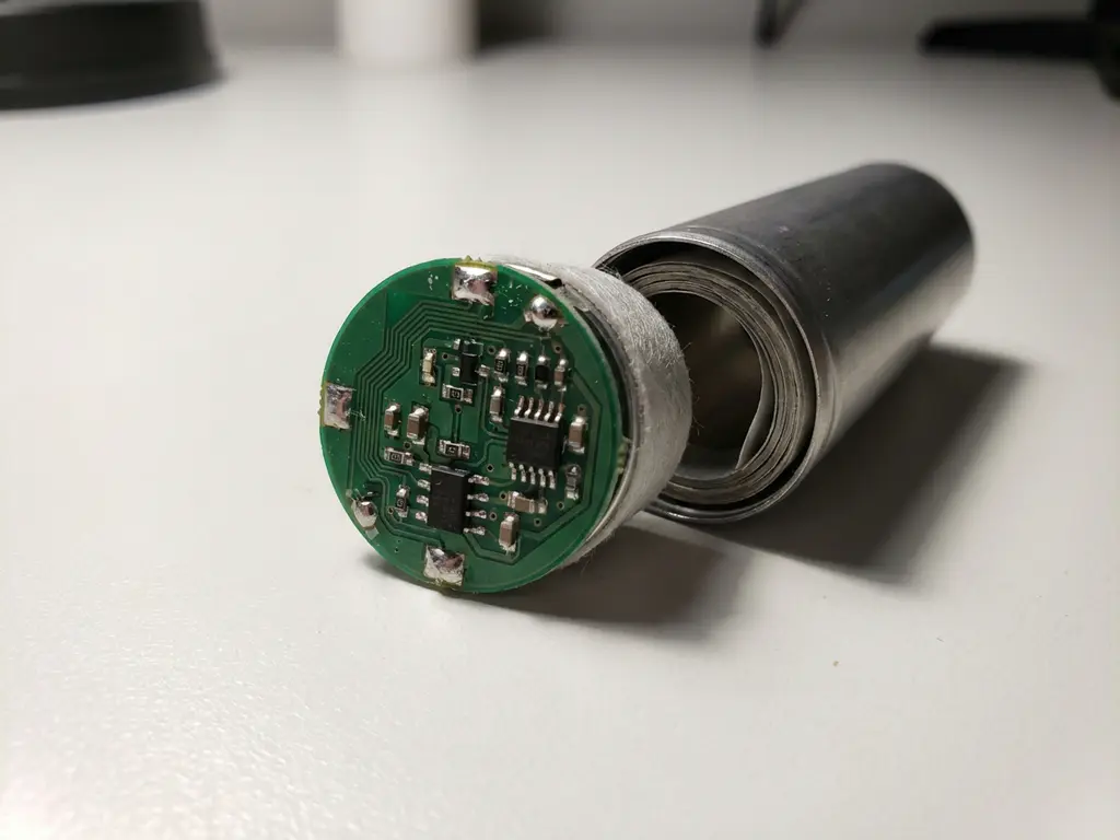
A protection circuit in a lithium-ion battery is an electronic module, typically based on a dedicated integrated circuit (IC), that monitors cell voltage, current, and temperature in real time and interrupts the charge or discharge path when any parameter exceeds a defined safe threshold. It sits between the cell terminals and the external contacts of the battery pack.
In practical terms, the protection circuit consists of a sensing IC paired with one or more field-effect transistors (FETs) that act as switches. When the IC detects an out-of-range condition, it drives the FET gate to open the circuit, cutting off current flow. This happens within milliseconds, before the cell chemistry can be driven into a thermally or electrochemically unstable state.
Protection circuits are found in single-cell configurations—such as those used in portable electronics—as well as in multi-cell packs, where they may operate in parallel with more sophisticated battery management electronics. In a research context, the relevant distinction is between the passive protection circuit embedded in a commercial cell and the active control logic applied by external test instrumentation.
Why do lithium-ion batteries need a protection circuit?
Lithium-ion cells require a protection circuit because their electrochemical stability window is narrow. Exceeding the upper voltage limit during charging, allowing deep discharge below a minimum voltage, or permitting excessive current flow can each trigger irreversible reactions—including lithium plating, electrolyte decomposition, and, in severe cases, thermal runaway.
The underlying chemistry explains the risk. Lithium-ion intercalation electrodes operate within specific potential ranges that maintain structural integrity. Charging a graphite anode beyond its lithiation capacity, for instance, forces metallic lithium deposition rather than intercalation. This lithium plating is not only a capacity-loss mechanism—it creates dendrites that can penetrate the separator and cause an internal short circuit.
On the cathode side, overcharging drives transition metal oxide materials into highly oxidised, thermally unstable states. The decomposition of the cathode at elevated states of charge releases oxygen, which can react exothermically with the organic electrolyte. A protection circuit prevents the cell from reaching these conditions under normal use.
How does a protection circuit detect and prevent overcharging?
A protection circuit detects overcharging by continuously comparing the cell terminal voltage against a fixed threshold—typically around 4.2 V for standard lithium cobalt oxide (LCO) chemistry, though the exact value varies by cathode material. When the measured voltage reaches this threshold, the IC signals the charge-control FET to open, interrupting the charge-current path immediately.
Voltage sensing and threshold triggering
The sensing IC samples cell voltage at high frequency, allowing it to respond to rapid voltage rises. The overcharge threshold is set during IC design and is not adjustable in most commercial protection circuits. This fixed threshold is calibrated to correspond to a state of charge at which further lithiation of the cathode would begin to compromise structural stability.
Hysteresis and reset behaviour
Most protection ICs incorporate a hysteresis band around the trigger threshold. Once the overcharge condition is detected and the FET opens, the circuit does not re-engage immediately when voltage drops slightly below the threshold. A defined voltage drop—the hysteresis offset—must occur before the charge path is restored. This prevents rapid switching that would otherwise occur near the threshold boundary.
In a laboratory setting, this behaviour is important to understand. If a potentiostat or galvanostat is driving a commercial cell and the protection circuit triggers, the instrument will see an open-circuit condition rather than a cell response. This can be misinterpreted as a measurement artefact if the researcher is unaware that the protection circuit has activated.
What are the main functions of a lithium-ion protection circuit?
The main functions of a lithium-ion battery protection circuit are overcharge protection, over-discharge protection, overcurrent protection, and short-circuit protection. Together, these four functions cover the primary failure modes that can lead to cell degradation or thermal runaway.
- Overcharge protection: Disconnects the charge path when cell voltage exceeds the upper threshold, preventing cathode instability and electrolyte oxidation.
- Over-discharge protection: Disconnects the discharge path when cell voltage falls below a minimum threshold, preventing copper current collector dissolution at the anode and irreversible capacity loss.
- Overcurrent protection: Monitors the current drawn from the cell and interrupts the discharge path if current exceeds a rated maximum, protecting against resistive heating and electrode damage.
- Short-circuit protection: Detects the near-instantaneous current surge caused by an external short and opens the FET within microseconds, limiting the energy delivered into the fault.
Some protection circuits also include temperature monitoring, though this function is more commonly associated with battery management systems in multi-cell packs. A basic single-cell protection circuit may rely on a positive temperature coefficient (PTC) thermistor as a passive thermal fuse rather than active temperature-based switching.
What is the difference between a protection circuit and a battery management system?
A protection circuit is a minimal, passive-logic safeguard that reacts to threshold violations by interrupting the circuit. A battery management system (BMS) is an active, programmable system that monitors, controls, and optimises cell operation across multiple parameters simultaneously—including state of charge (SoC) estimation, state of health (SoH) tracking, cell balancing, and communication with external systems.
The distinction matters in research contexts. A protection circuit operates on fixed hardware thresholds and has no memory, communication interface, or data output. It either allows current to flow or it does not. A BMS, by contrast, runs algorithms—often on a dedicated microcontroller—that can adapt charge and discharge limits based on measured cell history, temperature, and cycle count.
In multi-cell battery packs, the BMS also performs cell balancing: redistributing charge between cells in a series string to ensure no individual cell reaches an overcharge or over-discharge condition due to capacity mismatch. This function does not exist in a single-cell protection circuit.
For researchers designing or evaluating battery management strategies, the BMS represents the layer at which electrochemical knowledge translates into system-level control logic. Understanding the distinction between hardware protection and software-driven management is essential when interpreting charge-discharge data from pack-level experiments.
How does a faulty protection circuit affect battery research results?
A faulty or inappropriately triggered protection circuit can introduce significant artefacts into electrochemical measurements. If the protection circuit activates mid-cycle, it creates an abrupt open-circuit condition that appears in voltage-time or capacity-voltage profiles as an anomalous plateau or discontinuity—which may be incorrectly attributed to a phase transition or electrochemical event in the electrode material.
This is particularly relevant when researchers work with commercial cells rather than unprotected, research-grade electrodes. A protection circuit that triggers at a voltage close to the upper cut-off used in the experimental protocol will repeatedly interrupt cycling, producing inconsistent capacity values and distorted coulombic-efficiency measurements. Coulombic efficiency, which measures the ratio of charge extracted to charge inserted per cycle, is highly sensitive to any interruption in the current path.
Beyond voltage artefacts, a degraded protection circuit with increased internal resistance can add an uncontrolled series impedance to the cell. This impedance will appear in electrochemical impedance spectroscopy (EIS) measurements, potentially masking or distorting the contributions from the solid electrolyte interphase (SEI) layer, charge-transfer resistance, or electrolyte resistance that the researcher is attempting to characterise.
For reproducible results, researchers conducting fundamental electrode studies should use unprotected, research-grade electrochemical test cells where all boundary conditions are set explicitly by the test instrument, not by an embedded protection IC whose threshold values and response behaviour may not be fully documented.
How EL-Cell GmbH supports precise lithium-ion cell testing
When studying electrode materials and cell behaviour at the fundamental level, embedded protection circuits in commercial cells introduce variables that are difficult to control or account for. EL-Cell GmbH addresses this directly by providing electrochemical test cells designed for research use, where all operating limits are set by the connected instrumentation rather than by fixed-threshold protection ICs.
Our product portfolio supports controlled, reproducible electrochemical measurements across a range of experimental conditions:
- The PAT-Cell series provides standardised, unprotected test cells for half-cell and full-cell cycling, giving researchers complete control over voltage windows, current rates, and cut-off conditions.
- The PAT-Tester-i-16 integrates a galvanostat/potentiostat with EIS capability and a temperature-controlled cell chamber, allowing precise protocol definition without interference from external protection logic.
- The ECD-4-nano electrochemical dilatometer enables simultaneous electrochemical cycling and thickness measurement at sub-5 nm resolution—measurements that would be compromised by any uncontrolled circuit interruption.
- The ECC-Opto-10 supports in situ optical characterisation, where consistent, uninterrupted cycling is a prerequisite for meaningful data.
If you are designing experiments that require full control over electrochemical boundary conditions, contact us to discuss which test cell configuration and instrumentation setup best fits your research requirements.
Comments are closed.